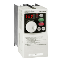
How to solve unknown cause after every check on Mitsubishi FR - S500 Inverter?
- TTamara ThomasJul 29, 2025
Initialize the parameters (return to factory settings), then reset the required parameter values and check again.

How to solve unknown cause after every check on Mitsubishi FR - S500 Inverter?
Initialize the parameters (return to factory settings), then reset the required parameter values and check again.
| Series | FR-S500 |
|---|---|
| Protection Class | IP20 |
| Control Method | V/f control |
| Overload Capacity | 150% for 60 seconds |
| Cooling Method | Forced air cooling |
| Protection Features | Overcurrent, Overvoltage, Undervoltage, Overheating, Short circuit |
| Communication Interfaces | RS-485 (Modbus RTU) |
| Operating Temperature | -10°C to +50°C |
| Storage Temperature | -20°C to +65°C |
| Ambient Humidity | 5% to 95% (non-condensing) |
| Altitude | Up to 1000m |
| Weight | Varies by model |
Crucial safety guidelines to prevent electric shock hazards when operating the inverter.
Provides essential wiring diagrams and specifications for connecting the inverter.
Details the layout and function of the inverter's main circuit connection terminals.
Explains how to use input signals for starting, stopping, and controlling the motor's rotation.
Details how to configure input terminals for multi-speed operation using RL, RM, RH, and REX signals.
A comprehensive list of all available inverter parameters and their basic settings.
Detailed explanations of inverter functions and how to configure parameters.
Parameters organized by their intended application for easier selection.
Adjusts inverter outputs (voltage, frequency) to match motor specifications.
Configures motor protection features and selects motor types for optimal performance.
Sets parameters for DC injection braking to control motor stopping characteristics.
Assigns specific functions to input terminals for flexible control.
Assigns specific functions to output terminals for status indication and alarms.
Configures PID control for process regulation like flow rate, air volume, or pressure.
Lists and explains various error codes and alarm indications displayed by the inverter.
Details major protective functions that cause the inverter to shut off output.
Provides detailed technical specifications for the inverter series.
Lists the electrical and performance ratings for different inverter models and power supplies.


 Loading...