6 Introduction of Functions
6.2 Basic Functions
53
FX3U-16CCL-M User's Manual
1
Introduction
2
Specification
3
System
Configuration
4
Installation
5
Wiring
6
Introduction of
Functions
7
Data Link
Processing
Time
8
Parameter
Setting
9
Data Link
Procedure
10
Buffer Memory
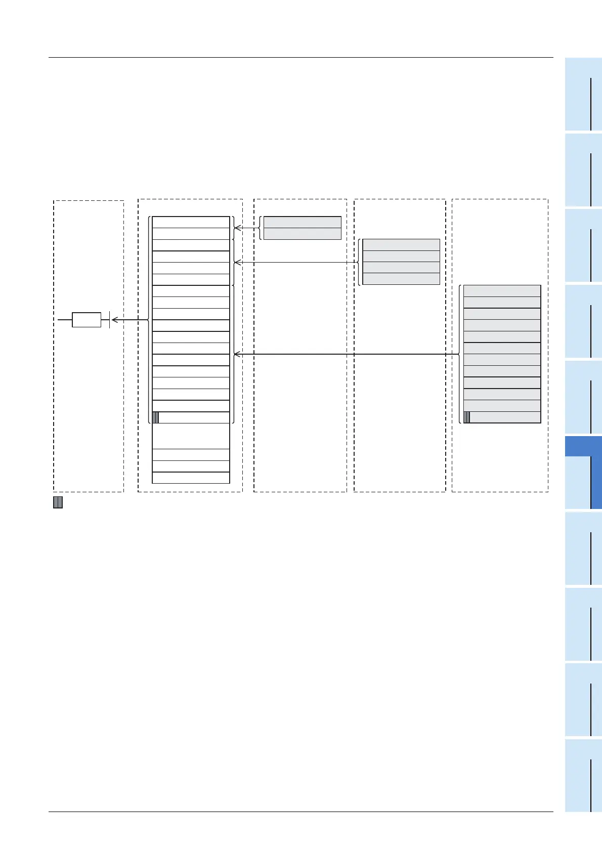
ON/OFF information from the remote I/O station/remote device station/intelligent device station to the
master station
3) The input status of the input (X) in the remote I/O station and the remote input (RX) in the remote device
station/intelligent device station is automatically (for each link scan) stored in the buffer memory "remote
input (RX)" in the master station.
4) The PLC receives the input status stored in the buffer memory "remote input (RX)" using the FROM
instruction.
Master station
Remote device station
(Station No. 1:
Occupies 1 station)
RX F to RX 0
RX 1F to RX 10
RX 2F to RX 20
RX 3F to RX 30
RX 4F to RX 40
RX 5F to RX 50
RX 6F to RX 60
RX 7F to RX 70
RX 8F to RX 80
RX 9F to RX 90
RX1EF to RX1E0
RX1FF to RX1F0
...
Remote input (RX)
X0F to X00
RX1DF to RX1D0
3)
4)
PLC
RX F to RX 0
RX 1F to RX 10
Remote device station
(Station No. 2:
Occupies 2 station)
3)
Remote input (RX)
Intelligent device station
(Station No. 4: Occupies 2
station,quadruple)
RX F to RX 0
3)
RX 1F to RX 10
RX 2F to RX 20
RX 3F to RX 30
RX 4F to RX 40
RX 5F to RX 50
RX 6F to RX 60
RX 7F to RX 70
: The last 2 bits cannot be used in the communication between the master and intelligent device stations.
Remote input (RX)
X1F to X10
RX 2F to RX 20
RX 3F to RX 30
RX AF to RX A0
RX BF to RX B0
RX CF to RX C0
RX DF to RX D0
RX EF to RX E0
RX FF to RX F0
RX10F to RX100
RX11F to RX110
RX 8F to RX 80
RX 9F to RX 90
RX AF to RX A0
RX BF to RX B0
FROM

 Loading...


