D-42
FX Series PLC User's Manual - Data Communication Edition
Computer Link
6 Control Procedures and Setting Methods
6.1 Data Flow by Link
6. Control Procedures and Setting Methods
6.1 Data Flow by Link
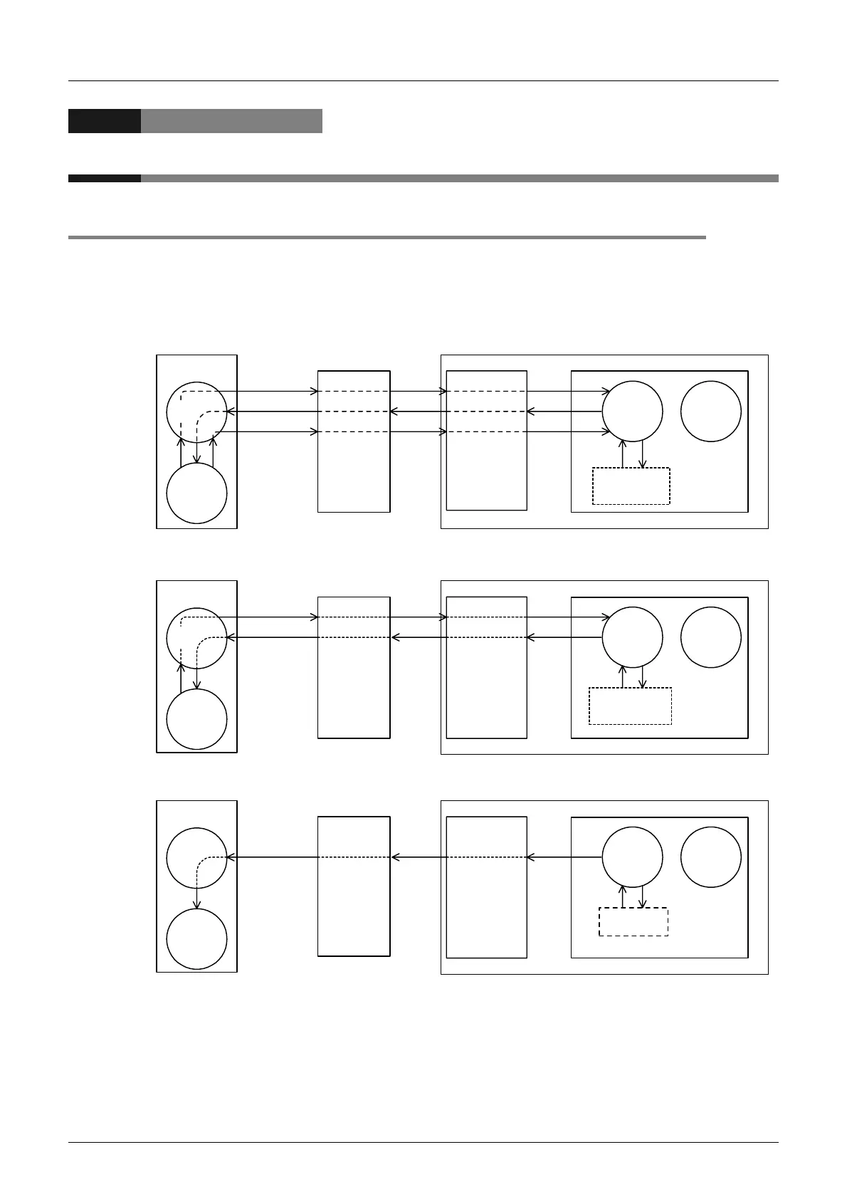
The figures below show images of data flow achieved when data is read from or written to a PLC CPU and
the status is controlled.
In the case of communication in accordance with RS-232C, ignore "485PC-IF" and regard "485ADP" as
"232ADP".
1. When the computer reads data from the PLC
2. When the computer writes data to the PLC
3. When the PLC sends data to the computer (on-demand function)
*1. The OS (standing for "Operating System") indicates the software used to efficiently operate the
resources including the CPUs, memories, terminals, files, and networks using user programs, etc.
Computer
OS
*1
Sequence
program
RS-232C
485PC-IF
RS-485
Device
memory, etc.
485ADP PLC CPU
[2] Command
[9] Various data
[12] Response
Device
memory
information
(read)
PLC CPU
information
(read)
[1] Request
[10] [11]
Interface for
signal
conversion
[3]
[8]
[13]
[4]
[7]
[14]
[6] Data
[5] Read
OS
*1
Computer
Sequence
program
RS-232C
485PC-IF
RS-485
485ADP PLC CPU
[2] Command,
data, etc.
[8] Response
Device
memory
information
(written)
PLC CPU
information
(written)
[3] [4]
[5] Write
[7]
[6]
Device
memory, etc.
[1] Request
OS
*1
OS
*1
Computer
OS
*1
Sequence
program
RS-232C
485PC-IF
RS-485
OS
*1
485ADP PLC CPU
[6] Data
[2]
Read
[5]
[4] Data
[7]
Write
On-demand
data
[3] Data
[1] Sending
request
+
Data writing
Device
memory, etc.
 Loading...


