H-32
FX Series PLC User's Manual - Data Communication Edition
Programming Communication
4 Connection Cables and Interfaces
4.2 Cable Connection Diagrams
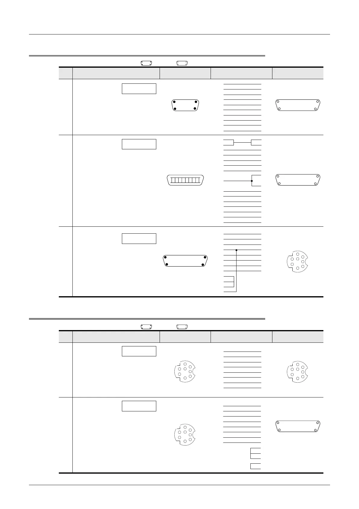
4.2.2 Connector conversion cable (commercial product) - No. B
4.2.3 FX-10P/FX-20P connection cable - No. C
No. Cable model name Application Connection diagram Application
Connector conversion
cable (normal type)
RS-232C
connection
B-1
9-pin D-Sub, female
51
96
25-pin D-Sub, male
113
14
25
Connector conversion
cable (normal type)
RS-232C
connection
B-2
25-pin D-Sub, male
113
14 25
14-pin Half-pitch
FG FG
3
8
4
7
9
8
3
6
7
4
1
5
2
5
2
6
20
SHELL SHELL
2
7
3
6
11
12
13
4
10
2
1
4
9
14
5
1
8
15
14
11
5
7
17
3
8
13
20
6
FX-20P-CADP
RS-422
connection
25-pin D-Sub, female
113
14
25
8-pin MINI-DIN, male
5
1
2
3
4
6
7
8
B-3
2
3
7
12
15
16
20
5
8
18
2
7
3
5
1
4
6
8
The connector shape indicates the engagement surface.
: Female type : Male type
24
21
22
24
22
8
17
14
No. Cable model name Application Connection diagram Application
FX-20P-CAB0
RS-422
connection
C-1
FX-20P-CAB
RS-422
connection
C-2
25-pin D-Sub, male
113
14
25
8-pin MINI-DIN, male
5
1
2
3
4
6
7
8
Programming tool
8-pin MINI-DIN, male
5
1
2
3
4
6
7
8
Programming tool
8-pin MINI-DIN, male
5
1
2
3
4
6
7
8
Communication port
connector
3
8
4
7
1
5
2
6
3
8
4
7
1
5
2
6
2
7
3
12
15
16
20
4
8
13
2
3
7
5
1
4
6
8
17
The connector shape indicates the engagement surface.
: Female type : Male type
24
21
 Loading...


