E-13
FX Series PLC User's Manual - Data Communication Edition
Inverter Communication
3 System Configuration and Selection
3.2 Applicable FX PLC and Communication Equipment
A
Common Items
B
N:N Network
C
Parallel Link
D
Computer Link
E
Inverter
Communication
F
Non-Protocol
Communication
(RS/RS2 Instruction)
G
Non-Protocol
Communication
(FX
2N
-232IF)
H
Programming
Communication
I
Remote
Maintenance
Apx.
Discontinued
models
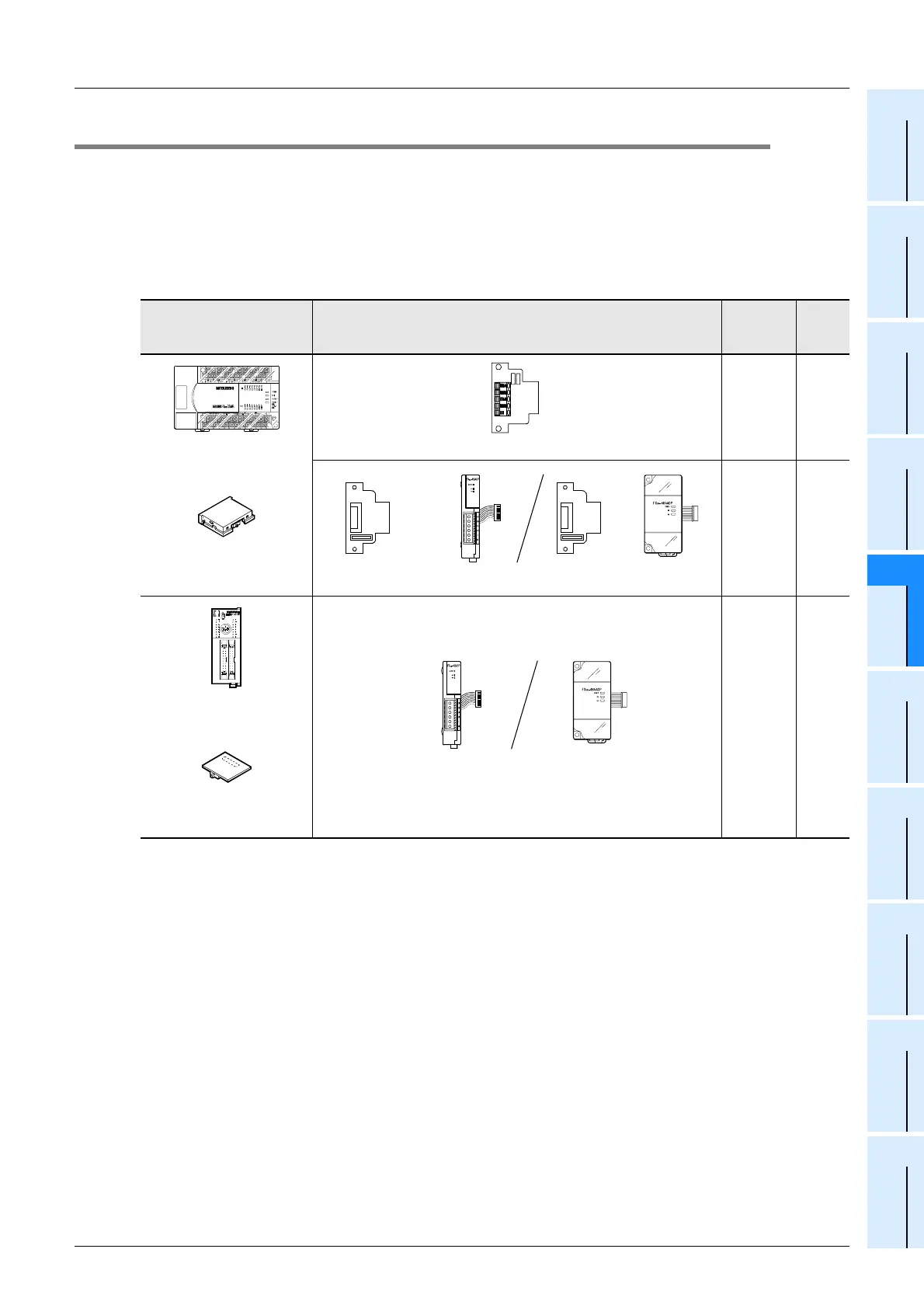
3.2 Applicable FX PLC and Communication Equipment
Select a (optional) communication equipment combination, and put a check mark in the "Check" column.
During selection, pay attention to the following:
-
In the table below, only the external dimensions are different between the units shown in "FX
2NC
-485ADP/
FX
0N
-485ADP".
Select either one.
- Inverter communication is not provided for the FX
0, FX0S, FX0N, FX1, FX2(FX), FX2C, FX1S, FX1N, and
FX
1NC Series.
FX Series Communication equipment (option)
Total
extension
distance
Check
50 m
(164' 0")
500 m
(1640' 5")
500 m
(1640' 5")
FX
2N
-ROM-E1
(Function extension
memory cassette)
FX
2N
+
FX
2N
-485-BD
FX
2N
-CNV-BD
+
FX
2NC
-485ADP
(European terminal block)
FX
0N
-485ADP
(Terminal block)
FX
2N
-CNV-BD
+
FX
2NC
-ROM-CE1
(Function extension
memory board)
1
+
FX
2NC
FX
2NC
-485ADP
(European terminal block)
FX
0N
-485ADP
(Terminal block)
 Loading...


