WELDING
BASE OF BODY REPAIR
9-5
NOTES REGARDING WELDING
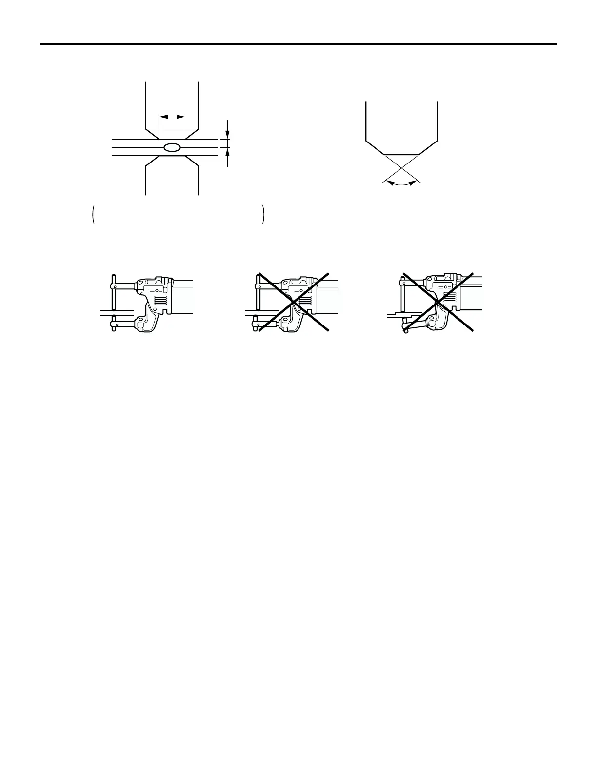
1. Selection of the electrode tips
• Select the electrode tips according to the
thickness of the panels to be welded.
D = 2t + 3 mm (D = 2t + 0.1 inch)
• The angle of the tip should be between 90
degree angle and 120 degree angle.
• To always keep the end of tip in the correct
shape, use a tip cutter, file or similar tool to
shape it if it becomes worn.
2. Alignment of the electrode tips
• Adjust the arms so that the upper and lower
electrode tips are in a straight line.
3. Alignment and length of the arms
• Adjust the electrode tips so that the upper and
lower arms are parallel.
• Select an appropriate arm length. Note, how-
ever, that the arm length should not be more
than 350 mm (13.8 inches) in order to ensure
nugget strength.
4. The weld points
• The overall strength will increase as the pitch
decreases; however, if the pitch decreases
too much, the current will be short-circuit
diverted to the previous weld point and the
strength of the individual nuggets will be insuf-
ficient.
• Make the spot welds at the center of the
flanges to provide sufficient adhesion. When
welding at an edge, make the spot welds at
least 5 mm (0.2 inch) from the edge of the
flange.
• The number of spot weld points should be the
same as, or slightly more than the number of
original repair welds.
• When spot welding three or more panels
together, if painted surfaces cause a loss of
conductivity, make the welds at the same
places as the factory welds. If this is done,
extra welds will not be necessary, but if extra
welds are necessary, switch to plug welding.
.
AB200030
AB
90˚ - 120˚
D
t
:
:
DIAMETER OF THE ELECTRODE TIP
THICKNESS OF THE PANEL
t
D

 Loading...