3. SIGNALS AND WIRING
3 - 62
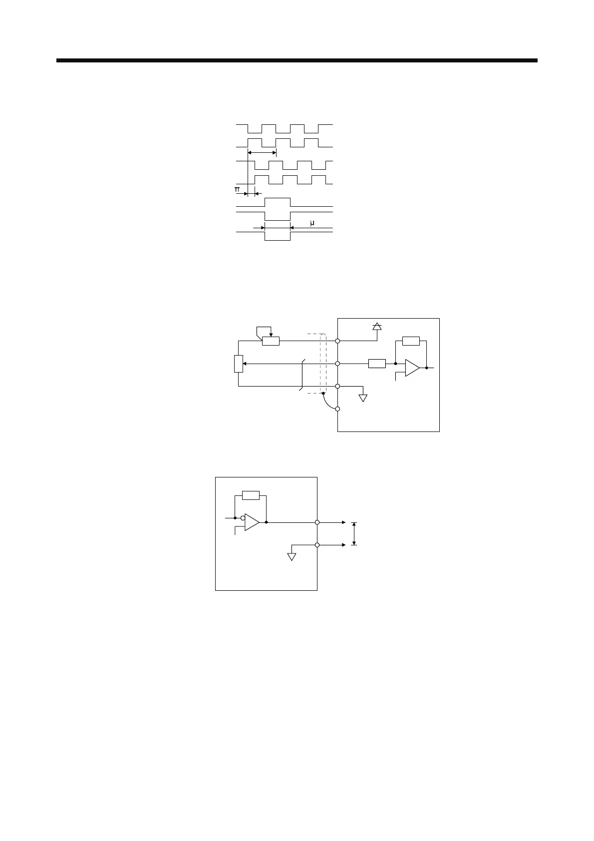
2) Output pulse
/2
T
400
s or more
Time cycle (T) is determined by the settings of
[Pr. PA15] and [Pr. PC19].
LA
LAR
LB
LBR
LZ
LZR
OP
Servo motor CCW rotation
(5) Analog input
Input impedance
10 kΩ to 12 kΩ
VC etc.
LG
P15R
SD
Approx.
10 kΩ
+15 V DC
Upper limit setting
2 kΩ
2 kΩ
Servo amplifie
(6) Analog output
Output voltage: ±10 V (Note)
Maximum output current: 1 mA
Resolution: 10 bits or equivalent
LG
MO1
(MO2)
Servo amplifie
Note. Output voltage range varies depending on the monitored signal.
 Loading...

