3. SIGNALS AND WIRING
3 - 25
3.4 Connectors and pin assignment
POINT
The pin assignment of the connectors are as viewed from the cable connector
wiring section.
For the STO I/O signal connector (CN8), refer to chapter 13.
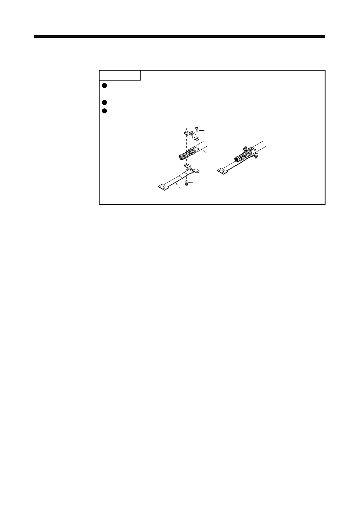
For the CN1 connector, securely connect the external conductive portion of the
shielded cable to the ground plate and fix it to the connector shell.
Screw
Screw
Ground plate
Cable
 Loading...

