1. FUNCTIONS AND CONFIGURATION
1 - 2
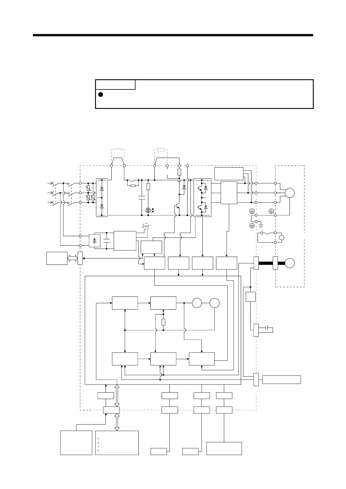
1.2 Function block diagram
The function block diagram of this servo is shown below.
POINT
The diagram shows MR-J4-_A_-RJ as an example. The MR-J4-_A_ servo
amplifier does not have the CN2L connector.
(1) 200 V class
(a) MR-J4-500A(-RJ) or less
U U
U
Model position
Current
control
Actual
position
control
Actual
speed
control
Virtual
motor
Virtual
encoder
L11
L21
Cooling fan
(Note 3)
Encoder
(Note 4)
N-CD
L3
L2
L1
Dynamic
brake
circuit
Power factor improving
DC reactor
Current
detection
Overcurrent
protection
Voltage
detection
(Note 2)
Power
supply
MCMCCB
Base
amplifier
STO
circuit
Position
command
input
Servo amplifier
U
V
W
U
V
W
P3 P4
Diode
stack
Relay
P+
+
+
B
RA
24 V DC
B1
B2
Optional battery
(for absolute position
detection system)
CN4
STO
switch
Model speed Model torque
M
CN2
CN8
Control
circuit
power
Model
position
control
Model
speed
control
Servo motor
CHARGE
lamp
Regene-
rative
TR
Current
encoder
Regenerative
option
CN5 CN3 CN6
Analog monitor
(two channel)
I/F
USB RS-422 D/AA/D
USB RS-422
Controller
Personal
computer
Analog
(two channel)
DI/O control
Servo-on
Input command pulse.
Start
Malfunction, etc
CN1
Electromagnetic
brake
Step-
down
circuit
(Note 1)
CN2L
External encoder
(Note 5)
(Note 6)
 Loading...

