3. SIGNALS AND WIRING
3 - 28
3.5 Signal (device) explanations
For the I/O interfaces (symbols in I/O division column in the table), refer to section 3.9.2. In the control mode
field of the table
P: Position control mode, S: Speed control mode, T: Torque control mode
: devices used with initial setting status, : devices used by setting [Pr. PA04] and [Pr. PD03] to [Pr.
PD28]
The pin numbers in the connector pin No. column are those in the initial status.
(1) I/O device
(a) Input device
Control
mode
Device Symbol
Connector
pin No.
Function and application
I/O
division
P S T
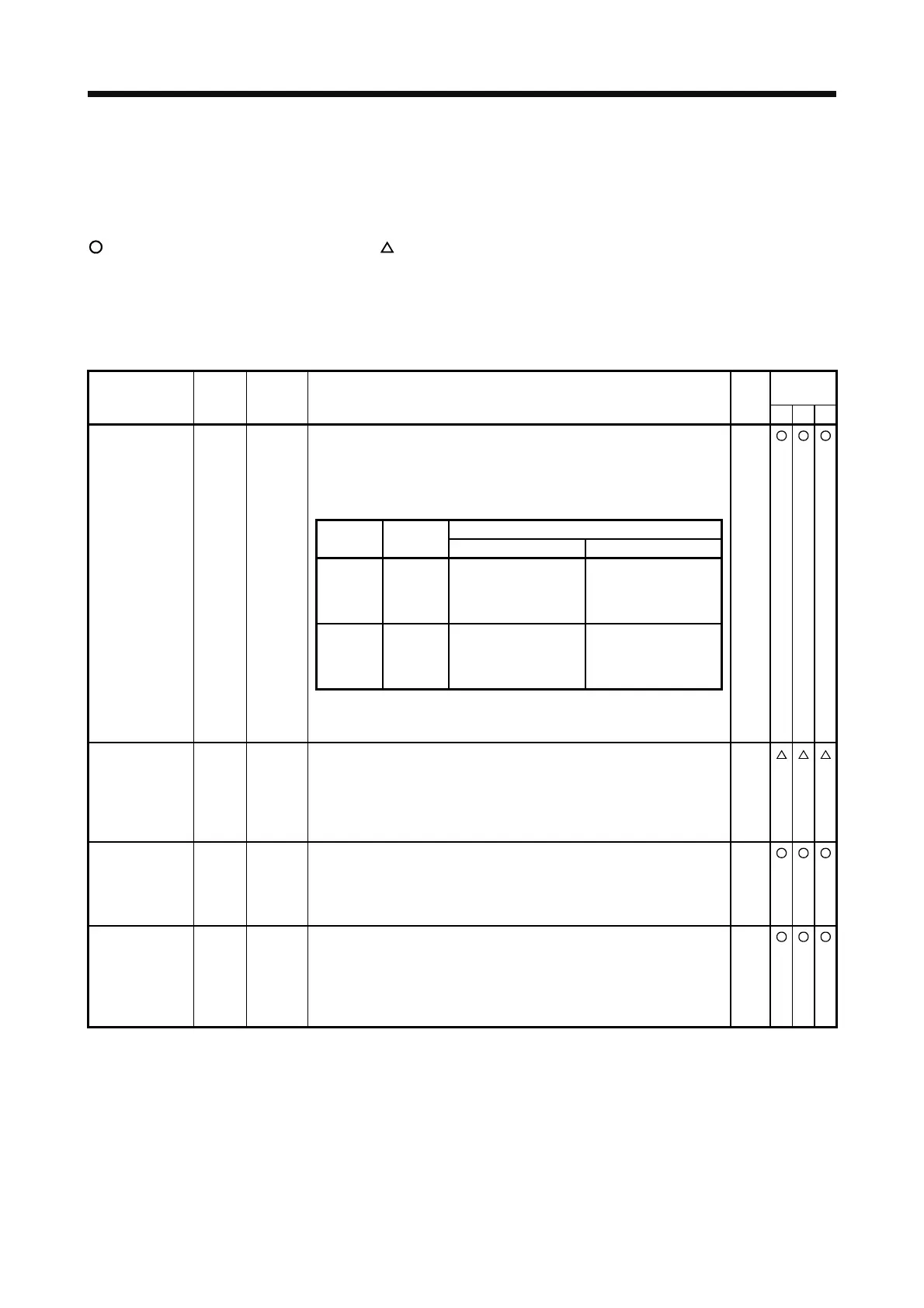
Turn off EM2 (open between commons) to decelerate the servo motor to a
stop with commands.
Turn EM2 on (short between commons) in the forced stop state to reset
that state.
The following shows the setting of [Pr. PA04].
Deceleration method
[Pr. PA04]
setting
EM2/EM1
EM2 or EM1 is off Alarm occurred
0 _ _ _ EM1
MBR (Electromagnetic
brake interlock) turns
off without the forced
stop deceleration.
MBR (Electromagnetic
brake interlock) turns
off without the forced
stop deceleration.
2 _ _ _ EM2
MBR (Electromagnetic
brake interlock) turns
off after the forced
stop deceleration.
MBR (Electromagnetic
brake interlock) turns
off after the forced
stop deceleration.
Forced stop 2 EM2 CN1-42
EM2 and EM1 are mutually exclusive.
EM2 has the same function as EM1 in the torque control mode.
DI-1
Forced stop 1 EM1 (CN1-42) When using EM1, set [Pr. PA04] to "0 _ _ _" to enable EM1.
Turn EM1 off (open between commons) to bring the motor to a forced stop
state. The base circuit is shut off, the dynamic brake is operated and
decelerate the servo motor to a stop.
Turn EM1 on (short between commons) in the forced stop state to reset
that state.
DI-1
Servo-on SON CN1-15 Turn SON on to power on the base circuit and make the servo amplifier
ready to operate. (servo-on status)
Turn it off to shut off the base circuit and coast the servo motor.
Set "_ _ _ 4" in [Pr. PD01] to switch this signal on (keep terminals
connected) automatically in the servo amplifier.
DI-1
Reset RES CN1-19 Turn on RES for more than 50 ms to reset the alarm.
Some alarms cannot be deactivated by RES (Reset). Refer to section 8.1.
Turning RES on in an alarm-free status shuts off the base circuit. The base
circuit is not shut off when " _ _ 1 _ " is set in [Pr. PD30].
This device is not designed to make a stop. Do not turn it on during
operation.
DI-1
 Loading...

