5. PARAMETERS
5 - 44
Control
mode
No./symbol/
name
Setting
digit
Function
Initial
value
[unit]
P S T
_ _ _ X Encoder pulse count polarity selection
Select a polarity of the linear encoder or load-side encoder.
0: Encoder pulse increases in the servo motor CCW or positive direction.
1: Encoder pulse decreases in the servo motor CCW or positive direction.
0h
_ _ X _ For manufacturer setting 0h
PC45
*COPA
Function
selection C-A
_ X _ _ Selection of A/B/Z-phase input interface encoder Z-phase connection judgement
function
Select the non-signal detection status for the pulse train signal from the A/B/Z-phase
input interface encoder used as a linear encoder or load-side encoder.
This function is enabled only when you use an A/B/Z-phase input interface encoder.
0h
Detection of
disconnection
Alarm status
Setting
value
Z-phase-side non-
signal
Fully closed
loop system
Linear servo
system
Direct drive
servo system
0 Enabled
[AL. 71.6]
(Z-phase)
[AL. 20.6]
(Z-phase)
[AL. 20.6]
(Z-phase)
1 Disabled
X _ _ _ For manufacturer setting 0h
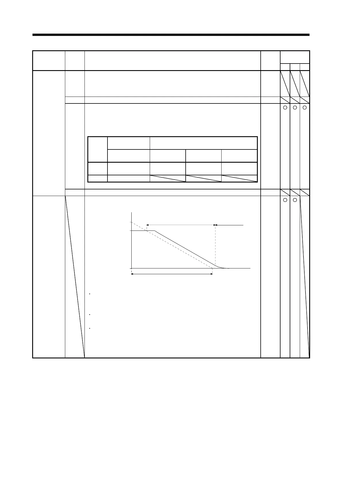
PC51
RSBR
Forced stop
deceleration
time constant
Set deceleration time constant when you use the forced stop deceleration function.
Set the time per ms from the rated speed to 0 r/min or 0 mm/s.
Forced stop deceleration
[Pr. PC51]
0 r/min
Servo motor speed
Rated speed
Dynamic brake
deceleration
(Linear servo
motor speed)
(0 mm/s)
[Precautions]
If the servo motor torque or linear servo motor thrust is saturated at the maximum
value during forced stop deceleration because the set time is too short, the time
to stop will be longer than the set time constant.
[AL. 50 Overload alarm 1] or [AL. 51 Overload alarm 2] may occur during forced
stop deceleration, depending on the set value.
After an alarm that leads to a forced stop deceleration, if an alarm that does not
lead to a forced stop deceleration occurs or if the control circuit power supply is
cut, dynamic braking will start regardless of the deceleration time constant setting.
Setting range: 0 to 20000
100
[ms]
 Loading...

