5. PARAMETERS
5 - 47
Control
mode
No./symbol/
name
Setting
digit
Function
Initial
value
[unit]
P S T
Any input device can be assigned to the CN1-15 pin.
_ _ x x Position control mode - Device selection
Refer to table 5.9.
02h
PD03
*DI1L
Input device
selection 1L
x x _ _ Speed control mode - Device selection
Refer to table 5.9.
02h
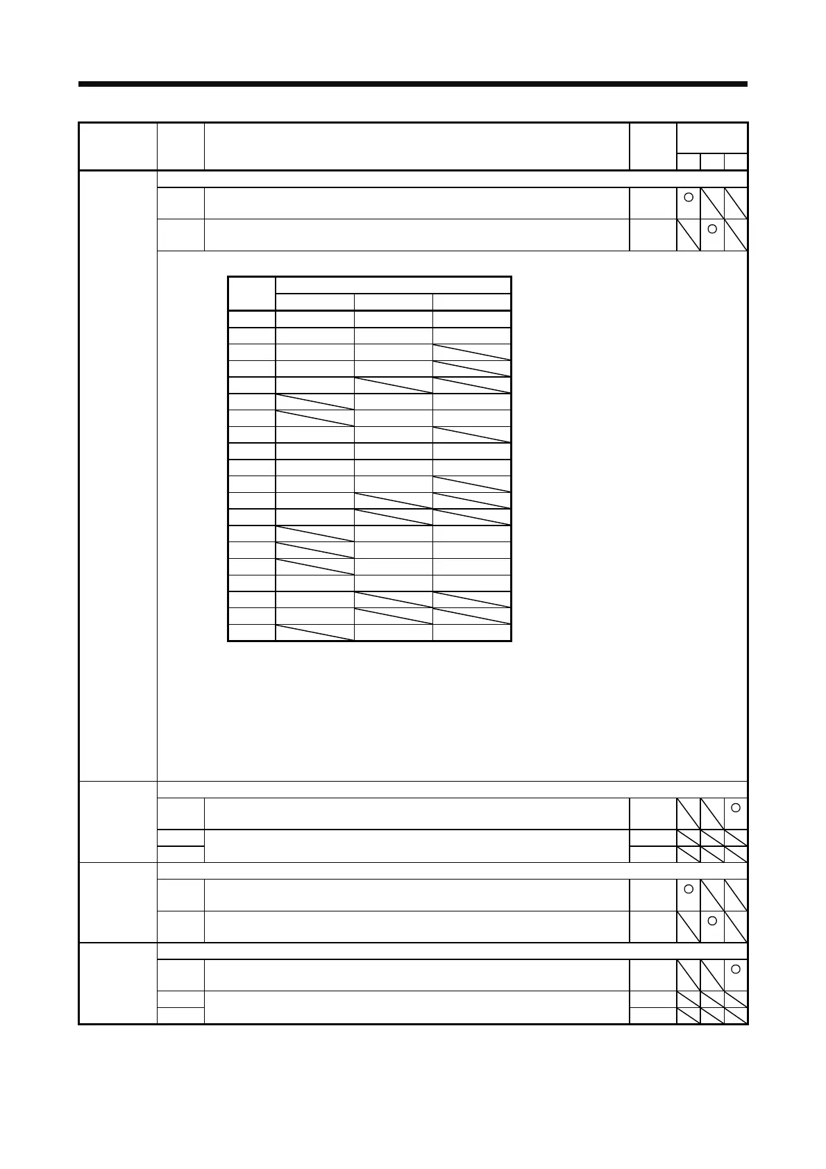
Table 5.9 Selectable input devices
Input device (Note 1)
Setting
value
P S T
02 SON SON SON
03 RES RES RES
04 PC PC
05 TL TL
06 CR
07 ST1 RS2
08 ST2 RS1
09 TL1 TL1
0A LSP LSP LSP (Note 3)
0B LSN LSN LSN (Note 3)
0D CDP CDP
0E CLD
0F MECR
20 SP1 SP1
21 SP2 SP2
22 SP3 SP3
23 LOP (Note 2) LOP (Note 2) LOP (Note 2)
24 CM1
25 CM2
26 STAB2 STAB2
Note 1. P: Position control mode, S: Speed control mode, T: Torque control mode
The diagonal lines indicate manufacturer settings. Never change the setting.
2. When assigning LOP (Control switching), assign it to the same pin in all control modes.
3. In the torque control mode, this device cannot be used during normal operation. It can be used
during the magnetic pole detection in the linear servo motor control mode and the DD motor
control mode. Also, when the magnetic pole detection in the torque control mode is completed,
this signal will be disabled.
Any input device can be assigned to the CN1-15 pin.
_ _ x x Torque control mode - Device selection
Refer to table 5.9 in [Pr. PD03] for settings.
02h
PD04
*DI1H
Input device
selection 1H
_ x _ _ For manufacturer setting 0h
x _ _ _ 0h
Any input device can be assigned to the CN1-16 pin.
_ _ x x Position control mode - Device selection
Refer to table 5.9 in [Pr. PD03] for settings.
00h
PD05
*DI2L
Input device
selection 2L
x x _ _ Speed control mode - Device selection
Refer to table 5.9 for settings.
21h
Any input device can be assigned to the CN1-16 pin.
_ _ x x Torque control mode - Device selection
Refer to table 5.9 in [Pr. PD03] for settings.
21h
PD06
*DI2H
Input device
selection 2H
_ x _ _ For manufacturer setting 0h
x _ _ _ 0h
 Loading...

