1. FUNCTIONS AND CONFIGURATION
1 - 18
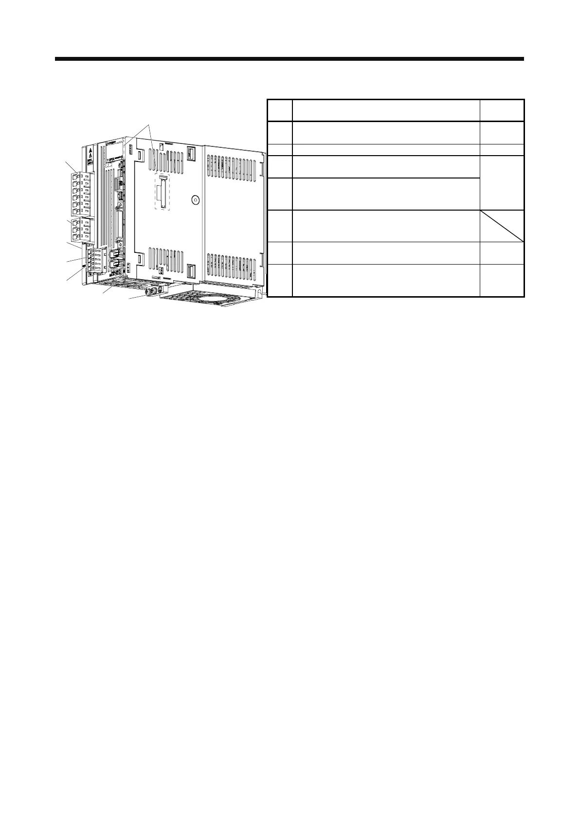
(b) MR-J4-350A(-RJ)
No. Name/Application
Detailed
explanation
(1)
Main circuit power supply connector (CNP1)
Connect the input power supply.
Section 3.1
Section 3.3
(2) Rating plate
Section 1.6
(3)
Servo motor power supply connector (CNP3)
Connect the servo motor.
(4)
Control circuit power supply connector (CNP2)
Connect the control circuit power supply and
regenerative option.
Section 3.1
Section 3.3
(5)
Charge lamp
When the main circuit is charged, this will light up.
While this lamp is lit, do not reconnect the cables.
(6)
Protective earth (PE) terminal
Grounding terminal
Section 3.1
Section 3.3
(7)
Battery holder
Install the the battery for absolute position data
backup.
Section
12.2
The broken line area is the same as
MR-J4-200A(-RJ) or less.
(1)
(3)
(2)
(4)
Side
(5)
(6)
(7)
 Loading...

