1. FUNCTIONS AND CONFIGURATION
1 - 24
Note 1. This is for MR-J4-_A4-RJ servo amplifier. MR-J4-_A4 servo
amplifier does not have CN2L connector.
2. "External encoder" is a term for linear encoder used in the linear
servo system and load-side encoder used in the fully closed
loop system in this manual.
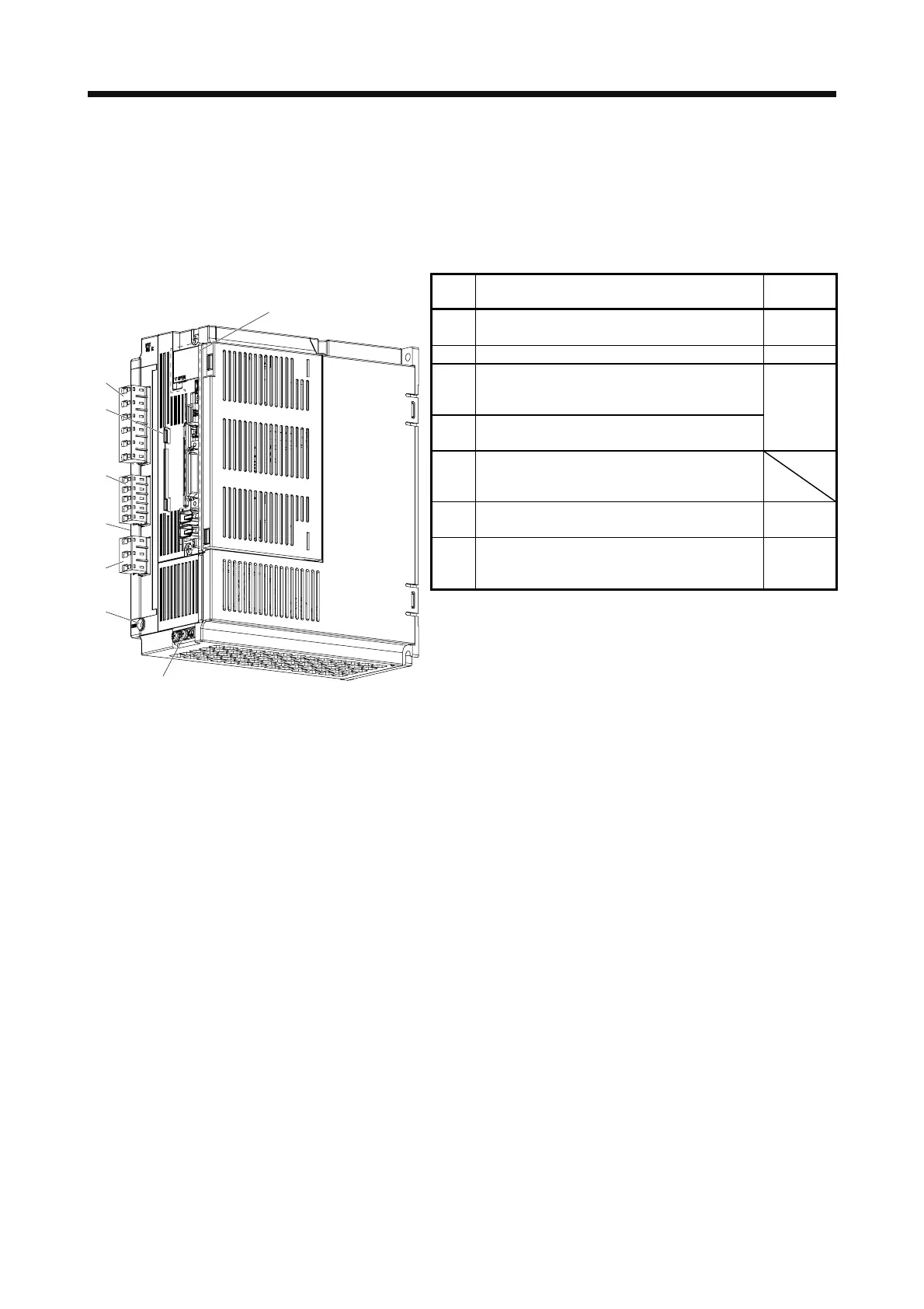
(b) MR-J4-350A4(-RJ)
No. Name/Application
Detailed
explanation
(1)
Main circuit power supply connector (CNP1)
Connect the input power supply.
Section 3.1
Section 3.3
(2) Rating plate Section 1.6
(3)
Control circuit power supply connector (CNP2)
Connect the control circuit power supply and
regenerative option.
(4)
Servo motor power output connector (CNP3)
Connect the servo motor.
Section 3.1
Section 3.3
(5)
Charge lamp
When the main circuit is charged, this will light.
While this lamp is lit, do not reconnect the cables.
(6)
Protective earth (PE) terminal
Grounding terminal
Section 3.1
Section 3.3
(7)
Battery holder
Install the battery for absolute position data
backup.
Section 12.2
(1)
(3)
(2)
Side
(4)
(5)
(6)
(7)
The broken line area is the same as
MR-J4-200A4(-RJ) or less.
 Loading...

