14. COMMUNICATION FUNCTION
14 - 2
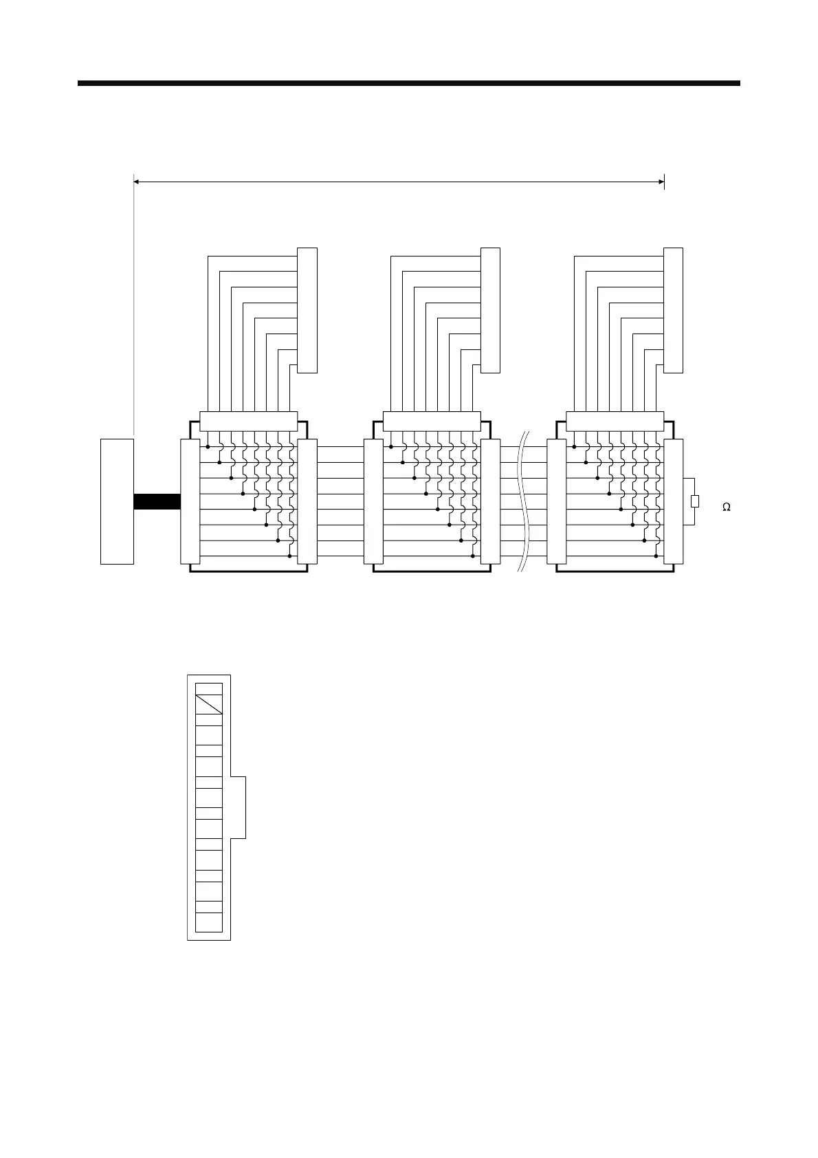
(b) Cable connection diagram
Wire the cables as follows.
(Note 6) Branch connector
(Note 4, 5)
LG
P5D
RDP
SDN
SDP
RDN
LG
NC
(Note 5)
1
2
3
4
5
6
7
8
1
2
3
4
5
6
7
8
1
2
3
4
5
6
7
8
12345678
(Note 6) Branch connector
(Note 4, 5)
(Note 1)
The second axis servo amplifier
Connector for CN3
(RJ45 Connector)
LG
P5D
RDP
SDN
SDP
RDN
LG
NC
(Note 5)
1
2
3
4
5
6
7
8
1
2
3
4
5
6
7
8
1
2
3
4
5
6
7
8
12345678
(Note 6) Branch connector
(Note 4, 5)
(Note 1, 7)
The n axis servo amplifier
Connector for CN3
(RJ45 Connector)
LG
P5D
RDP
SDN
SDP
RDN
LG
NC
1
2
3
4
5
6
7
8
1
2
3
4
5
6
7
8
1
2
3
4
5
6
7
8
12345678
(Note 2)
150
RDP
RDN
(Note 3) 30 m or less
(Note 8)
Note 1. Recommended connector (Hirose Electric)
Plug: TM10P-88P
Connection tool: CL250-0228-1
The following shows pin assignment viewed from connector wiring section.
8
6
7
RDN
5
SDP
4
SDN
3
RDP
2
P5D
1
LG
LG
2. The final axis must be terminated between RDP (pin No.3) and RDN (pin No.6) on the receiving side (servo amplifier) with
a 150 Ω resistor.
3. The overall length is 30 m or less in low-noise environment.
4. The wiring between the branch connector and servo amplifier should be as short as possible.
5. Use the EIA568-compliant cable (10BASE-T cable, etc.).
6. Recommended branch connector: BMJ-8 (Hachiko Electric)
7. n ≤ 32 (Up to 32 axes can be connected.)
8. RS-422/232C conversion cable DSV-CABV (Diatrend)
 Loading...

