APPENDIX
App. - 10
App. 4.4 Electrical Installation and configuration diagram
WARNING
Turn off the molded-case circuit breaker (MCCB) to avoid electrical shocks or
damages to the product before starting the installation or wiring.
CAUTION
The installation complies with IEC/EN 60204-1. The voltage supply to machines
must be 20 ms of tolerance against instantaneous power failures as specified in
IEC/EN 60204-1.
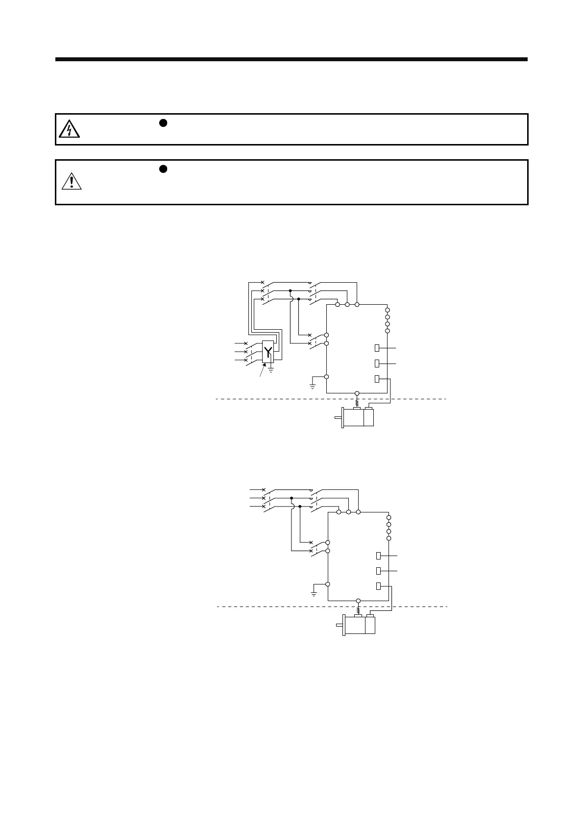
The following shows representative configuration examples to conform to the IEC/EN/UL/CSA standards.
(1) 3-phase input for MR-J4 1-axis servo amplifier
(a) 200 V class
MCCB
or fuse
Controller
STO
Encoder cable
(3-phase
230 V AC)
Power
supply
(3-phase
400 V AC)
Transformer
(star-connected)
(Note)
MCCB
or fuse
PE
L11
L21
MC
Servo amplifier
Cabinet side
Machine side
Encoder
Servo motor
L1
C
P+
D
N-
U/V/W/PE
CN2
CN1
CN8
L2L3
Note. When the wire sizes of L1 and L11 are the same, MCCB or fuse is not required.
(b) 400 V class
MCCB
or fuse
Controller
STO
Encoder cable
(3-phase
00 V AC)
(Note)
MCCB
or fuse
PE
L11
L21
MC
Servo amplifier
Cabinet side
Machine side
Encoder
Servo motor
L1
C
P+
D
N-
U/V/W/PE
CN2
CN1
CN8
L2L3
Note. When the wire sizes of L1 and L11 are the same, MCCB or fuse is not required.
 Loading...

