14. COMMUNICATION FUNCTION
14 - 28
14.5.6 Disabling/enabling I/O devices (DIO)
You can disable inputs regardless of the I/O device status. When inputs are disabled, the input signals
(devices) are recognized as follows. However, EM2 (Forced stop 2), LSP (Forward rotation stroke end), and
LSN (Reverse rotation stroke end) cannot be disabled.
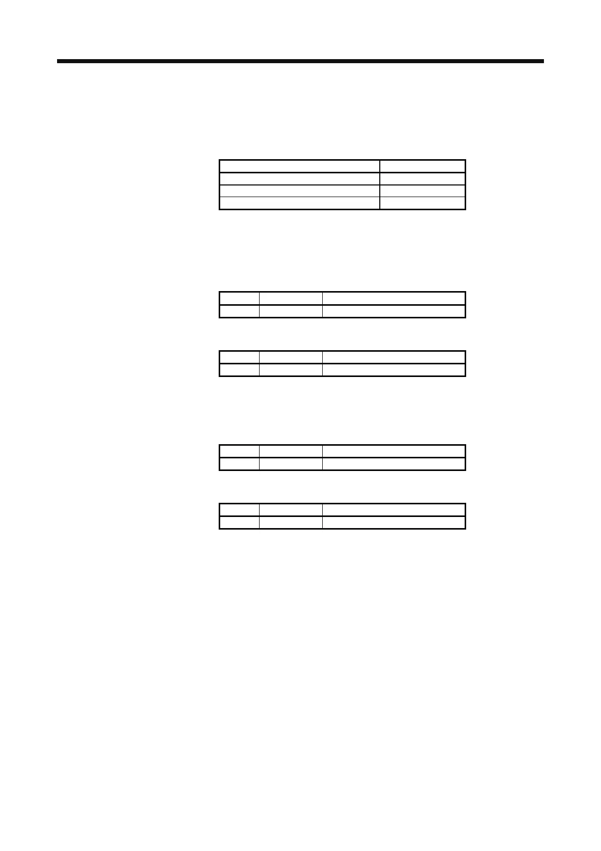
Signal Status
Input device (DI) Off
External analog input signal 0 V
Pulse train input None
(1) Disabling/enabling the input devices (DI), external analog input signals and pulse train inputs except
EM2 (Forced stop 2), LSP (Forward rotation stroke end), and LSN (Reverse rotation stroke end).
Transmit the following communication commands.
(a) Disabling
Command Data No. Data
[9] [0] [0] [0] 1EA5
(b) Enabling
Command Data No. Data
[9] [0] [1] [0] 1EA5
(2) Disabling/enabling the output devices (DO)
Transmit the following communication commands.
(a) Disabling
Command Data No. Data
[9] [0] [0] [3] 1EA5
(b) Enabling
Command Data No. Data
[9] [0] [1] [3] 1EA5