3
1. Safety precautions
• For installation and relocation work, follow the instructions in the installation
manual and use tools and pipe components specically made for using with
refrigerant specied in the outdoor unit installation manual.
Caution:
• Perform grounding.
Do not connect the ground wire to a gas pipe, water pipe arrester or
telephone ground wire. Defective grounding could cause an electric shock.
• Do not install the unit in a place where an inammable gas leaks.
If gas leaks and accumulates in the area surrounding the unit, it could
cause an explosion.
• Install a ground leakage breaker depending on the installation place (where
it is humid).
If a ground leakage breaker is not installed, it could cause an electric shock.
• If the air conditioner is installed in a small room or closed room, measures
must be taken to prevent the refrigerant concentration in the room from
exceeding the safety limit in the event of refrigerant leakage. Should the
refrigerant leak and cause the concentration limit to be exceeded, hazards
due to lack of oxygen in the room may result.
• Perform the drainage/piping work securely according to the installation
manual.
If there is a defect in the drainage/piping work, water could drop from the
unit and household goods could be wet and damaged.
• Fasten a are nut with a torque wrench as specied in this manual.
When fastened too tight, a flare nut may broken after a long period and
cause a leakage of refrigerant.
2. Selecting the installation location
2.1. Indoor unit
• Whereairowisnotblocked.
• Where cool air spreads over the entire room.
• Where it is not exposed to direct sunshine.
• At a distance 1 m or more away from your TV and radio (to prevent picture from
beingdistortedornoisefrombeinggenerated).
2.2. Outdoor unit
• Where it is not exposed to strong wind.
• Whereairowisgoodanddustless.
• Where it is not exposed to rain and direct sunshine.
• Where neighbours are not annoyed by operation sound or hot air.
• Where rigid wall or support is available to prevent the increase of operation
sound or vibration.
• Where there is no risk of combustible gas leakage.
• Wheninstallingtheunitatahighlevel,besuretoxtheunitlegs.
• Where it is at least 3 m away from the antenna of TV set or radio. (Otherwise,
imageswouldbedisturbedornoisewouldbegenerated.)
• Inaplaceasfar awayaspossiblefromuorescentandincandescentlights(so
theinfraredremotecontrolcanoperatetheairconditionernormally).
• Wheretheairltercanberemovedandreplacedeasily.
• Indoor units must be installed in a ceiling with a minimum height of 2.5 meters.
Warning:
Mount the indoor unit into a ceiling strong enough to withstand the weight of
the unit.
• Install the unit horizontally.
Caution:
Avoid the following places for installation where air conditioner trouble is
liable to occur.
• Where there is too much machine oil.
• Salty environment as seaside areas.
• Hot-spring areas.
• Where sulde gas exists.
• Other special atmospheric areas.
3. Selecting an installation site & Accessories
•
Selectasitewithsturdyxedsurfacesucientlydurableagainsttheweightofunit.
• Before installing unit, the routing to carry in unit to the installation site should be
determined.
• Selectasitewheretheunitisnotaectedbyenteringair.
• Selectasitewheretheowofsupplyandreturnairisnotblocked.
• Select a site where refrigerant piping can easily be led to the outside.
• Select a site which allows the supply air to be distributed fully in room.
• Do not install unit at a site with oil splashing or steam in much quantity.
•
Donotinstallunitatasitewherecombustiblegasmaygenerate,owin,stagnate
or leak.
• Do not install unit at a site where equipment generating high frequency waves (a
highfrequencywavewelderforexample)isprovided.
• Donotinstallunitatasitewhereredetectorislocatedatthesupplyairside.(Fire
detector may operate erroneously dew to the heated air supplied during heating
operation.)
• When special chemical product may scatter around such as site chemical plants
and hospitals, full investigation is required before installing unit. (The plastic
componentsmaybedamageddependingonthechemicalproductapplied.)
• If the unit is run for long hours when the air above the ceiling is at high
temperature/highhumidity(dewpointabove26°C),dewcondensationmay
be produced in the indoor unit. When operating the units in this condition, add
insulation material (10-20 mm) to the entire surface of the indoor unit to avoid
dew condensation.
3.1. Install the indoor unit on a ceiling strong enough
to sustain its weight
Warning:
The unit must be securely installed on a structure that can sustain its weight.
If the unit is mounted on an unstable structure, it may fall down causing
injuries.
3.2. Securing installation and service space
Secure enough access space to allow for the maintenance, inspection, and
replacement of the motor, fan, drain pump, heat exchanger, and electric box in one
of the following ways.
Select an installation site for the indoor unit so that its maintenance access space will
not be obstructed by beams or other objects.
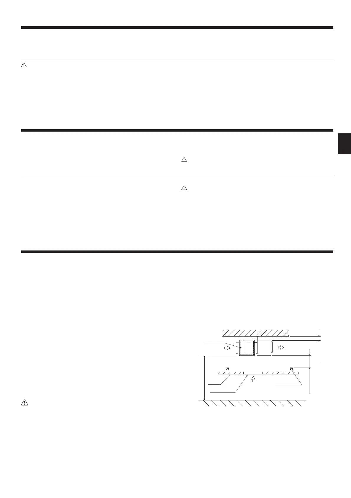
(1)Whenaspaceof300mmormoreisavailable belowtheunitbetweentheunit
and the ceiling. [Fig. 3-2-1]
• Create access door 1 and 2 as shown in [Fig. 3-2-2].
(Access door 2 is not required if enough space is available below the unit for
amaintenanceworkertoworkin.)
•
An access hole of the same size as the access door 3 as shown in [Fig. 3-2-4]
is required to access drain pan or heat exchanger for replacement.
(Requiredonlywhentheceilingmaterialcannotberemoved.)
(2)Whenaspaceoflessthan300mmisavailablebelowtheunitbetweentheunit
and the ceiling.
•
Create access door 3 below the electric box and the unit as shown in [Fig. 3-2-4].
[Fig. 3-2-1]
Air outlet
Air inlet
Control box
Access door 1
Ceiling
Ceiling beam
Min. 20mm
Z
Min. 2500mm

 Loading...