16
9. Test run
• If the unit cannot be operated properly after the above test run has been performed, refer to the following table to remove the cause.
Symptom
Cause
Wired remote controller LED1,2(PCBinoutdoorunit)
PLEASE WAIT
For about 2 minutes
following power-on
After LED 1, 2 are lighted, LED 2 is turned
o,thenonlyLED1islighted.(Correct
operation)
• For about 2 minutes after power-on, operation of the
remote controller is not possible due to system start-up.
(Correctoperation)
PLEASE WAIT
→
Error code
After about 2
minutes has expired
following power-on
Only LED 1 is lighted.
→
LED 1, 2 blink.
• Connector for the outdoor unit’s protection device is not
connected.
• Reverse or open phase wiring for the outdoor unit’s power
terminalblock(L1,L2,L3)
Display messages do not appear
even when operation switch is
turned ON (operation lamp does
notlightup).
Only LED 1 is lighted.
→
LED 1, 2 blinks
twice, LED 2 blinks once.
• Incorrect wiring between indoor and outdoor units (incorrect
polarityofS1,S2,S3)
• Remote controller wire short
On the wireless remote controller with conditions above, following phenomena takes place.
• No signals from the remote controller are accepted.
• OPE lamp is blinking.
• The buzzer makes a short ping sound.
Note:
Operation is not possible for about 30 seconds after cancellation of function selection. (Correct operation)
FordescriptionofeachLED(LED1,2,3)providedontheindoorcontroller,refertothefollowingtable.
LED1(powerformicrocomputer) Indicates whether control power is supplied. Make sure that this LED is always lit.
LED2(powerforremotecontroller) Indicates whether power is supplied to the remote controller. This LED lights only in the case of
the indoor unit which is connected to the outdoor unit refrigerant address “0”.
LED3(communicationbetweenindoorandoutdoorunits)
Indicates state of communication between the indoor and outdoor units. Make sure that this LED is
always blinking.
9.4. AUTO RESTART FUNCTION
Indoor controller board
This model is equipped with the AUTO RESTART FUNCTION.
When the indoor unit is controlled with the remote controller, the operation mode, set temperature, and the fan speed are memorized by the indoor controller board.
The auto restart function sets to work the moment the power has restored after power failure, then, the unit will restart automatically.
SettheAUTORESTARTFUNCTIONusingtheremotecontroller.(Modeno.01)
10. Maintenance
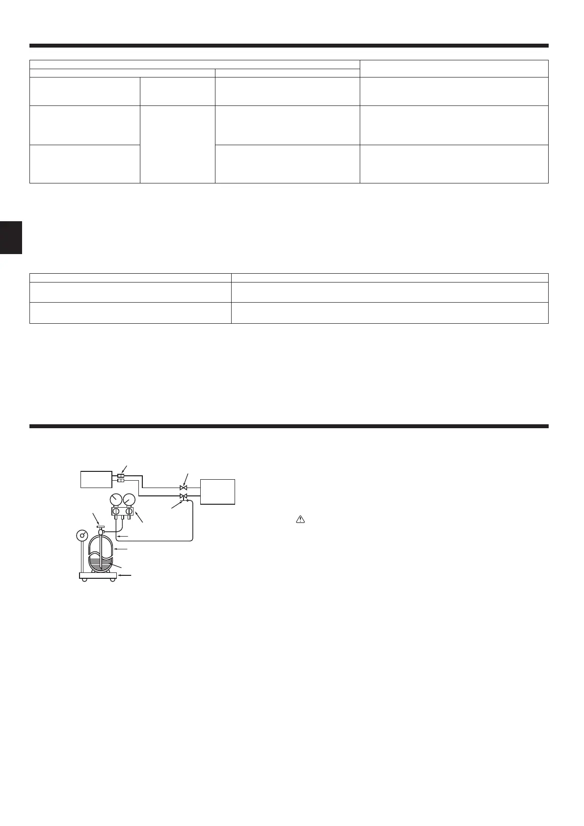
10.1. Gas charge
[Fig. 10-1]
Ⓐ
Ⓖ
Ⓗ
Ⓚ
Ⓛ
Ⓜ
Ⓘ
Ⓙ
Ⓒ
Ⓓ
Ⓔ
Ⓕ
Ⓐ
Indoor unit
Ⓑ
Union
Ⓒ
Liquid pipe
Ⓓ
Gas pipe
Ⓔ
Stop valve
Ⓕ
Outdoor unit
Ⓖ
Refrigerant gas cylinder operating valve
Ⓗ
Refrigerant gas cylinder for R32/R410A with siphon
Ⓘ
Refrigerant(liquid)
Ⓙ
Electronic scale for refrigerant charging
Ⓚ
Chargehose(forR32/R410A)
Ⓛ
Gaugemanifoldvalve(forR32/R410A)
Ⓜ
Service port
1. Connect gas cylinder to the service port of stop valve (3-way).
2. Execute air purge of the pipe (or hose) coming from refrigerant gas
cylinder.
3. Replenish specified amount of refrigerant, while running the air
conditioner for cooling.
Note:
Incaseofaddingrefrigerant,complywiththequantityspeciedfortherefrigerating
cycle.
Caution:
• Do not discharge the refrigerant into the atmosphere.
Take care not to discharge refrigerant into the atmosphere during
installation, reinstallation, or repairs to the refrigerant circuit.
• For additional charging, charge the refrigerant from liquid phase of the gas
cylinder.
If the refrigerant is charged from the gas phase, composition change may
occur in the refrigerant inside the cylinder and the outdoor unit. In this
case, ability of the refrigerating cycle decreases or normal operation can be
impossible. However, charging the liquid refrigerant all at once may cause
the compressor to be locked. Thus, charge the refrigerant slowly.
To maintain the high pressure of the gas cylinder, warm the gas cylinder with warm
water(under40°C)duringcoldseason.Butneverusenakedreorsteam.

 Loading...