13
8. Electrical work
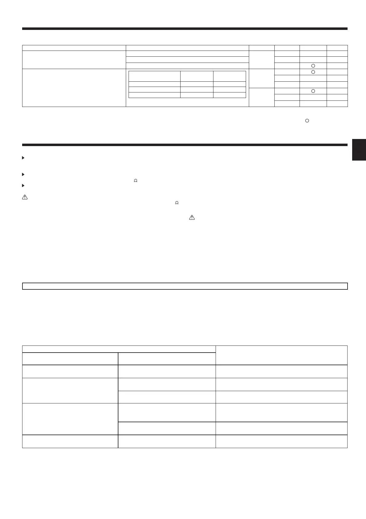
Function table 2
Select unit number AL [wired remote controller]/07 [wireless remote controller]
Mode Settings Mode no. Setting no. Initial setting Check
Filter sign
100 Hr
07
1
2500 Hr 2
Noltersignindicator 3
External static pressure
External static
pressure
Setting no. of
mode no. 08
Setting no. of
mode no. 10
50 Pa 1 1
100 Pa 2 1
150 Pa 3 1
08
1
2
3
10
1
2
3
*1 When the power supply returns, the air conditioner will start 3 minutes later.
Note: When the function of an indoor unit were changed by function selection after the end of installation, always indicate the contents by entering a
or other mark in the
appropriatecheckledofthetables.
9. Test run
9.1. Before test run
After completing installation and the wiring and piping of the indoor and
outdoor units, check for refrigerant leakage, looseness in the power supply or
control wiring, wrong polarity, and no disconnection of one phase in the supply.
Use a 500-volt megohmmeter to check that the resistance between the
power supply terminals and ground is at least 1.0 M
Ω
.
Do not carry out this test on the control wiring (low voltage circuit)
terminals.
Warning:
Do not use the air conditioner if the insulation resistance is less than 1.0 M
Ω
.
Insulation resistance
After installation or after the power source to the unit has been cut for an
extended period, the insulation resistance will drop below 1 M
Ω
due to refrigerant
accumulating in the compressor. This is not a malfunction. Perform the following
procedures.
1. Remove the wires from the compressor and measure the insulation resistance
of the compressor.
2. If the insulation resistance is below 1 M
Ω
, the compressor is faulty or the
resistance dropped due the accumulation of refrigerant in the compressor.
3. After connecting the wires to the compressor, the compressor will start to warm
up after power is supplied. After supplying power for the times indicated below,
measure the insulation resistance again.
• The insulation resistance drops due to accumulation of refrigerant in the
compressor. The resistance will rise above 1 M
Ω
after the compressor is
warmed up for two to three hours.
(The time necessary to warm up the compressor varies according to
atmosphericconditionsandrefrigerantaccumulation.)
• To operate the compressor with refrigerant accumulated in the compressor,
the compressor must be warmed up at least 12 hours to prevent breakdown.
4. If the insulation resistance rises above 1 M
Ω
, the compressor is not faulty.
Caution:
• The compressor will not operate unless the power supply phase connection
is correct.
• Turn on the power at least 12 hours before starting operation.
- Starting operation immediately after turning on the main power switch can result
in severe damage to internal parts. Keep the power switch turned on during the
operational season.
9.2. Test run
9.2.1. Using wired remote controller (option)
n
Makesuretoreadoperationmanualbeforetestrun.(Especiallyitemstosecuresafety)
Step 1 Turn on the power.
• Remotecontroller:Thesystemwillgointostartupmode,andtheremotecontrollerpowerlamp(green)and“PLEASEWAIT”willblink.Whilethelampandmessageare
blinking, the remote controller cannot be operated. Wait until “PLEASE WAIT” is not displayed before operating the remote controller. After the power is turned on, “PLEASE
WAIT” will be displayed for approximately 2 minutes.
• Indoorcontrollerboard:LED1willbelitup,LED2willbelitup(iftheaddressis0)oro(iftheaddressisnot0),andLED3willblink.
• Outdoorcontrollerboard:LED1(green)andLED2(red)willbelitup.(Afterthestartupmodeofthesystemnishes,LED2willbeturnedo.)Iftheoutdoorcontroller
board uses a digital display, [- ] and [ -] will be displayed alternately every second.
If the operations do not function correctly after the procedures in step 2 and thereafter are performed, the following causes should be considered and eliminated if they
are found.
(Thesymptomsbelowoccurduringthetestrunmode.“Startup”inthetablemeanstheLEDdisplaywrittenabove.)
Symptoms in test run mode
Cause
Remote Controller Display
OUTDOOR BOARD LED Display
< > indicates digital display.
Remote controller displays “PLEASE WAIT”, and
cannot be operated.
After “startup” is displayed, only green lights up.
<00>
• After power is turned on, “PLEASE WAIT” is displayed for 2
minutesduringsystemstartup.(Normal)
After power is turned on, “PLEASE WAIT” is
displayed for 3 minutes, then error code is
displayed.
After“startup”isdisplayed,green(once)andred
(once)blinkalternately.<F1>
• Incorrect connection of outdoor terminal block. (R, S, T and S
1
,
S
2
, S
3
)
After“startup”isdisplayed,green(once)andred
(twice)blinkalternately.<F3,F5,F9>
• Outdoor unit’s protection devise connector is open.
No display appears even when remote controller
operation switch is turned on. (Operation lamp
doesnotlightup.)
After“startup”isdisplayed,green(twice)andred
(once)blinkalternately.<EA.Eb>
• Incorrect wiring between the indoor and outdoor unit. (Polarity is
wrong for S
1
, S
2
, S
3
)
• Remote controller transmission wire short.
After “startup” is displayed, only green lights up.
<00>
• Thereisnooutdoorunitofaddress0.(Addressisotherthan0.)
• Remote controller transmission wire open.
Display appears but soon disappears even when
remote controller is operated.
After “startup” is displayed, only green lights up.
<00>
• After canceling function selection, operation is not possible for
about30seconds.(Normal)

 Loading...