4
3. Selecting an installation site & Accessories
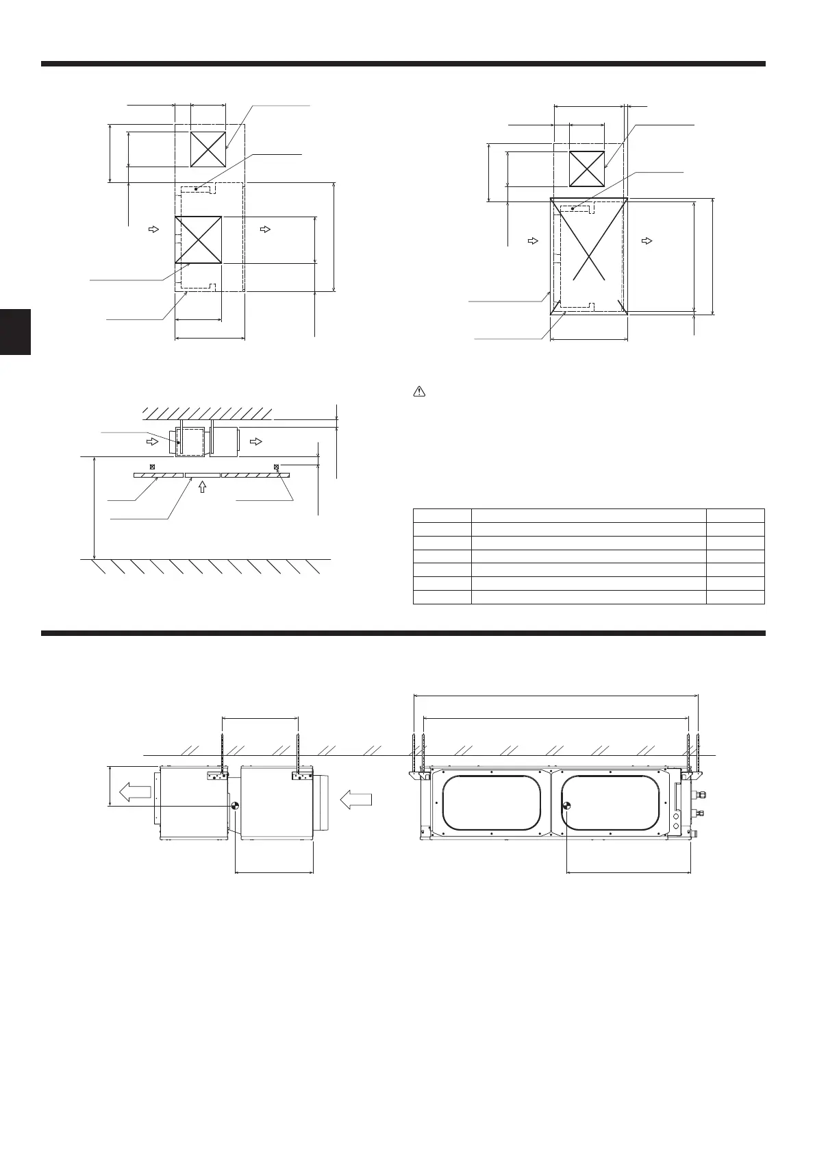
[Fig. 3-2-2]
Control box
Access door 2
(600 × 600)
Access door 1
(450 × 450)
450100 ~ 200
150 ~ 200 450
Min. 750
Bottom of
indoor unit
(Viewed from the direction of the arrow Z)
Maintenance
access space
Air
outlet
Air
inlet
600
600
900
350 ~ 400
1405
[Fig. 3-2-3]
Min. 2500mm
Air outletAir inlet
Control box
Access door 1
Ceiling Ceiling beam
Min. 20mm
Min. 20mm
Y
[Fig. 3-2-4]
Control box
Access door 1
(450 × 450)
50
(Viewed from the direction of the arrow Y)
Air
outlet
1505
140550
900
450
100 ~ 200
Access door 3
150 ~ 200 450
Min. 750
Maintenance
access space
Air
inlet
1000
Bottom of
indoor unit
Warning:
• This unit should be installed in rooms which exceed the oor space specied
in outdoor unit installation manual. Refer to outdoor unit installation manual.
• Install the indoor unit at least 2.5m above oor or ground level. For appliances
not accessible to the general public.
• Refrigerant pipes connection shall be accessible for maintenance purpose.
3.3. Indoor unit accessories
The unit is provided with the following accessories:
Part No. Name Quantity
1 Washer(withcushion) 4
2 Washer(withoutcushion) 4
3 Socket 1
4 Pipecover(small) 1
5 Pipecover(large) 1
6 Band 7
4. Fixing hanging bolts
4.1. Fixing hanging bolts
[Fig. 4-1]
1474
393
400
190
1374
680
(Givesiteofsuspensionstrongstructure.)
Hanging structure
•
Ceiling: The ceiling structure varies from building to one another. For detailed information, consult your construction company.
• If necessary, reinforce the hanging bolts with anti-quake supporting members as countermeasures against earthquakes.
*UseM10forhangingboltsandanti-quakesupportingmembers(eldsupply).
①
Reinforcingtheceilingwithadditionalmembers(edgebeam,etc.)mustberequiredtokeeptheceilingatlevelandtopreventtheceilingfromvibrations.
②
Cut and remove the ceiling members.
③
Reinforcetheceilingmembers,andaddothermembersforxingtheceilingboards.

 Loading...