9
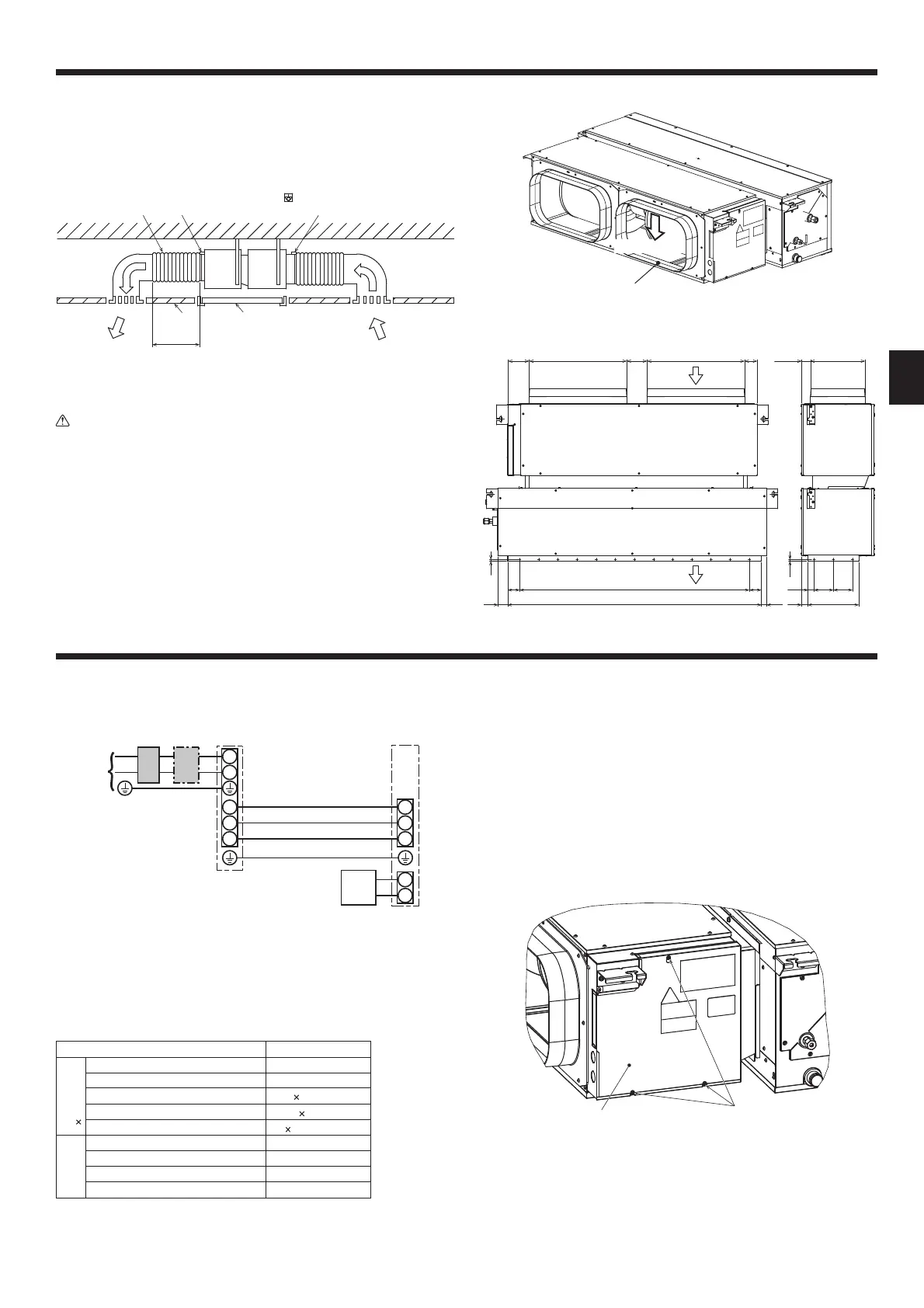
7. Duct work
• In connecting duct, insert canvas duct between unit and duct.
• Use incombustible material for duct parts.
• Provide full insulation to inlet duct ange, outlet duct ange and outlet duct to
prevent condensation.
• Besuretoapplytheairlterneartheairinletgrille.
• Beforeconnectinganinletduct,installtheairlterintheinletgrille.
[Fig. 7-1-1]
Ⓒ
Ⓔ
Ⓖ
Ⓖ
Ⓓ
Ⓕ
ⒶⒷ
Ⓐ
Air inlet
Ⓔ
Canvas duct
Ⓑ
Air outlet
Ⓕ
Keep duct-work length 850 or more
Ⓒ
Access door
Ⓖ
Connect common reference potential wire between
duct-work to air conditioner
Ⓓ
Ceiling surface
Caution:
• Inlet duct of 850 mm or more should be construted.
To connect the air conditioner main body and the duct for potential
equalization.
•
To reduce the risk of injury from metal sheet edges, wear protective gloves.
• Install sucient thermal insulation to prevent condensation forming on
outlet duct anges and outlet ducts.
• To avoid electrical noise interference, do not run transmission lines at the
bottom of the unit.
• To prevent damage to the inlet ange, install the duct so that a load of
3 kg or heavier will not be applied to the inlet ange. [Fig. 7-1-2]
• Mount holes for outlet duct ange and inlet duct. [Fig. 7-1-3]
• The return-air-temperature thermistor is located directly behind the
control box and senses the temperature of the air passing through the
ange closest to the control box.
[Fig. 7-1-2]
Inlet frangeInlet frange
Less than 3 kgLess than 3 kg
[Fig. 7-1-3]
8. Electrical work
8.1. Power supply
8.1.1. Indoor unit power supplied from outdoor unit
[Fig. 8-1]
S1
S2
L
N
1
2
S1
S2
S3
S3
Ⓐ
Ⓔ
Ⓕ
ⒼⒹ
Ⓑ Ⓒ
Ⓐ
Outdoor unit power supply
Ⓑ
Earth leakage breaker
Ⓒ
Wiring circuit breaker or isolating switch
Ⓓ
Outdoor unit
Ⓔ
Indoor unit/outdoor unit connecting cables
Ⓕ
Remote controller
Ⓖ
Indoor unit
Field electrical wiring
Indoor unit model PEA
Wiring Wire No.
×
size (mm
2
)
Indoorunitpowersupply(Heater)
–
Indoorunitpowersupply(Heater)earth
–
Indoor unit-Outdoor unit
3
×
1.5(polar)
Indoor unit-Outdoor unit earth
1 × Min. 1.5
Remote controller-Indoor unit *1
2 ×0.3(Non-polar)
Circuit
rating
Indoorunit(Heater)L-N *2
–
Indoor unit-Outdoor unit S1-S2 *2
230 V AC
Indoor unit-Outdoor unit S2-S3 *2
24 V DC
Remote controller-Indoor unit *2
14 V DC
*1. The 10 m wire is attached in the remote controller accessory. Max. 500 m
*2.TheguresareNOTalwaysagainsttheground.
S3 terminal has 24 V DC against S2 terminal. However between S3 and S1, these terminals
are not electrically insulataed by the transformer or other device.
Notes: 1. Wiring size must comply with the applicable local and national
code.
2. Power supply cords and indoor unit/outdoor unit connecting
cords shall not be lighter than polychloroprene sheathed exible
cord. (Design 245 IEC57)
3. Install an earth longer than other cables.
4. Indoor and outdoor connecting wires have polarities. Make sure to
match the terminal number (S1, S2, S3) for correct wirings.
5. Wiring for remote controller cable shall be apart (5 cm, 2 inch or
more) from power source wiring so that it is not influenced by
electric noise from power source wiring.
8.2. Indoor wire connection
Please identify the model name of the operation manual attached on the terminal
block box with that shown on the rating name plate.
1. Loosen the three screws holding the cover to dismount the cover.
[Fig. 8-2-1]
Ⓑ
Ⓐ
Ⓐ
Screws
Ⓑ
Cover
52
1325 (Outlet Duct)
62 100 × 12 = 1200
110 510 (Inlet duct) 106 510 (Inlet duct)
34
33
100 100
10
47.5
266
285
(Inlet duct)
66
28
62
(Outlet duct)
Air
outlet
Air
inlet

 Loading...