10
8. Electrical work
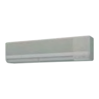
2. Open knockout holes
(Recommendtouseascrewdriverorthelikeforthiswork.)
[Fig. 8-2-2]
Ⓒ
Ⓒ
knockout hole
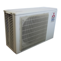
3. Fixindoorunit/outdoorunitconnectingwiretoterminalblockboxbyusingbuer
bushingfortensileforce.(PGconnectionorthelike.)Connectremotecontroller
cable to terminal block through the knockout hole of terminal block box using
ordinary bushing.
[Fig. 8-2-3]
Ⓖ
Ⓔ
Ⓓ
Ⓕ
Ⓓ
Use PG bushing to keep the weight of the cable and external force from being
applied to the power supply terminal connector. Use a cable tie to secure the cable.
Ⓔ
Remote controller cable
Ⓕ
Use ordinary bushing
Ⓖ
Indoor unit/outdoor unit connecting wire
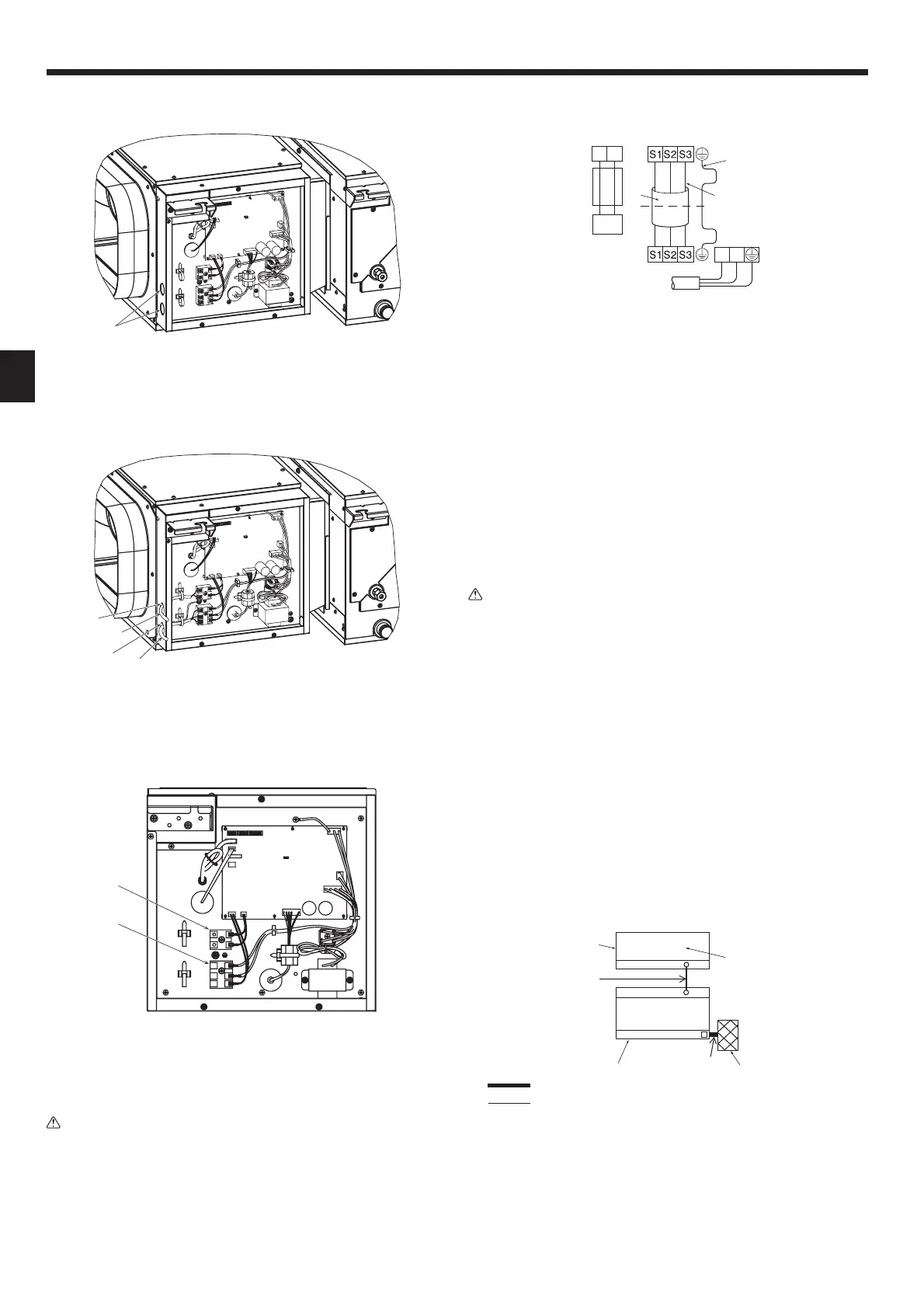
[Fig. 8-2-4]
Ⓗ
Ⓘ
Ⓗ
Terminal block for indoor unit/outdoor unit connecting wire
Ⓘ
Terminal block for remote controller cable
4. After wiring is complete, make sure again that there is no slack on the
connections, and attach the cover onto the terminal block box in the reverse
order of removal.
Warning:
• Attach the electrical part cover securely. If it is attached incorrectly, it could
result in a re, electric shock due to dust, water, etc.
• Use the specified indoor/outdoor unit connecting wire to connect the
indoor and outdoor units and x the wire to the terminal block securely so
that no stress is applied to the connecting section of the terminal block.
Incomplete connection or xing of the wire could result in a re.
• Do not pinch the cables or wires when attaching the terminal block box
cover. Doing so may cause a risk of disconnection.
•
When accommodating the terminal block box, make sure that the connectors
on the box side are not removed. If removed, it cannot operate normally.
[Fig. 8-2-5]
1 2
②
④
③
⑦
L
N
①
Ⓓ
Ⓑ
Ⓒ
Ⓐ
Indoor terminal block
Ⓑ
Earthwire(green/yellow)
Ⓒ
Indoor/outdoor unit connecting wire 3-core 1.5 mm
2
or more
Ⓓ
Outdoor terminal block
Ⓔ
Power supply cord : 2.0 mm
2
or more
①
Connecting cable
Cable 3-core 1.5 mm
2
, in conformity with Design 245 IEC 57.
②
Indoor terminal block
③
Outdoor terminal block
④
Always install an earth wire (1-core 1.5 mm
2
)longerthanothercables
⑤
Remote controller cable
Wire No × size (mm
2
):Cable2C×0.3
This wire accessory of remote controller
(wirelength:10m,non-polar.Max.500m)
⑥
Wiredremotecontroller(option)
⑦
Power supply cord
Cable 3-core 2.0 mm
2
or more, in conformity with Design 245 IEC 57.
• Perform wiring as shown in [Fig. 8-2-5].(Procurethecablelocally.)
Make sure to use cables of the correct polarity only.
• Connect the terminal blocks as shown in [Fig. 8-2-5].
Caution:
• Use care not to make mis-wiring.
• Firmly tighten the terminal screws to prevent them from loosening.
• After tightening, pull the wires lightly to conrm that they do not move.
8.3.
Remote controller (wireless remote controller
(option))
8.3.1. For wireless remote controller (option)
1) Installation area
• Area in which the remote controller is not exposed to direct sunshine.
• Area in which there is no near by heating source.
• Areainwhichtheremotecontrollerisnotexposedtocold(orhot)winds.
• Area in which the remote controller can be operated easily.
• Area in which the remote controller is beyond the reach of children.
*Thesignalcantraveluptoapproximately7meters(inastreightline)within45degreesto
both right and left of the center line of the receiver.
*
Connect the infrared remote controller signal receiver sensor to the circuit board on the A-side.
2) Installing procedures
Refer to the installation manual that comes with each remote controller for details.
8.3.2. Signal Receiving Unit
1) Sample system connection
[Fig. 8-3-1]
②
IC
control board A
OC(00)
CN90
TB1
TB4
①
Ⓒ
Ⓑ
①
Signal receiving unit wiring
②
Indoor/outdoor wiring
Ⓐ
Outdoor unit
Ⓑ
Refrigerant address
Ⓒ
Indoor unit
Ⓓ
Signal receiving unit
Only the wiring from the signal receiving unit and between the remote controllers is
shown in [Fig. 8-3-1].Thewiringdiersdependingontheunittobeconnectedor
the system to be used.
For details on restrictions, refer to the installation manual or the service handbook
that came with the unit.

 Loading...