7
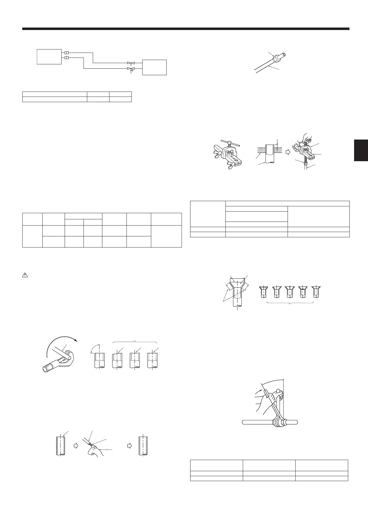
6. Refrigerant piping work
6.1. Refrigerant pipe
[Fig. 6-1]
øB
øA
ⓐ
ⓑ
ⓐ
Indoor unit
ⓑ
Outdoor unit
Model A B
PEA-M100, 125, 140 ø15.88 ø9.52
Refer to the Instruction Manual that came with the outdoor unit for the restrictions on
theheightdierencebetweenunitsandfortheamountofadditionalrefrigerant
charge.
Avoid the following places for installation where air conditioner trouble is liable to
occur.
• Where there is too much oil such as for machine or cooking.
• Salty environment as seaside areas.
• Hot-spring areas.
• Wheresuldegasexists.
• Other special atmospheric areas.
• Thisunithasaredconnectionsonbothindoorandoutdoorsides.[Fig. 6-1]
• Insulate both refrigerant and drainage piping completely to prevent condensation.
Piping preparation
• Refrigerant pipes of 3, 5, 7, 10 and 15 m are available as optional items.
(1)Tablebelowshowsthespecicationsofpipescommerciallyavailable.
Model Pipe
Outside diameter
Min wall
thickness
Insulation
thickness
Insulation
material
mm inch
PEA-
M100,
125, 140
For liquid 9.52 3/8 0.8 mm 8 mm
Heat resisting
foam plastic
0.045specic
gravity
For gas 15.88 5/8 1.0 mm 8 mm
(2)Ensurethatthe2refrigerantpipesarewellinsulatedtopreventcondensation.
(3)Refrigerantpipebendingradiusmustbe10cmormore.
Caution:
Using careful insulation of specied thickness. Excessive thickness prevents
storage behind the indoor unit and smaller thickness causes dew drippage.
6.2. Flaring work
• Maincauseofgasleakageisdefectinaringwork.
Carryoutcorrectaringworkinthefollowingprocedure.
6.2.1. Pipe cutting
[Fig. 6-2-1]
ⓐ
ⓓ
ⓔ
90°
ⓐ
Copper tubes
ⓓ
Tilted
ⓑ
Good
ⓔ
Uneven
ⓒ
No good
ⓕ
Burred
• Using a pipe cutter cut the copper tube correctly.
6.2.2. Burrs removal
[Fig. 6-2-2]
ⓓ
ⓒ
ⓐ
ⓐ
Burr
ⓒ
Spare reamer
ⓑ
Copper tube/pipe
ⓓ
Pipe cutter
• Completely remove all burrs from the cut cross section of pipe/tube.
• Put the end of the copper tube/pipe to downward direction as you remove burrs
in order to avoid burrs drop in the tubing.
6.2.3. Putting nut on
[Fig. 6-2-3]
ⓐ
Flare nut
ⓑ
Copper tube
• Remove arenuts attached to indoor and outdoor unit, then put them on pipe/
tube having completed burr removal.
(notpossibletoputthemonafteraringwork)
• Usethearenutincludedwiththisindoorunit.
6.2.4. Flaring work
[Fig. 6-2-4]
ⓔ
ⓑ
ⓒ
ⓓ
ⓒ
ⓐ
Flaring tool
ⓓ
Flare nut
ⓑ
Die
ⓔ
Yoke
ⓒ
Copper tube
• Carryoutaringworkusingaringtool.
Pipe diameter
(mm)
Dimension
A(mm)
B(mm)
When the tool for R32/R410A
is used
Clutch type
9.52 0 - 0.5 13.2
15.88 0 - 0.5 19.7
Firmly hold copper tube in a die in the dimension shown in the table at above.
• Whenreconnectingthedetachedrefrigerantpipes,makesuretoarethemagain.
6.2.5. Check
[Fig. 6-2-5]
ⓓ ⓔ ⓕ ⓖ ⓗ
ⓐ
Smooth all around
ⓕ
Scratchonaredplane
ⓑ
Inside is shining without any scratches
ⓖ
Cracked
ⓒ
Even length all around
ⓗ
Uneven
ⓓ
Too much
ⓘ
Bad examples
ⓔ
Tilted
• Comparethearedworkwithagureinrightsidehand.
•
Ifareisnotedtobedefective,cutothearedsectionanddoaringworkagain.
6.3. Pipe connection
[Fig. 6-3-1]
• Apply a thin coat of refrigeration oil on the seat surface of pipe.
• Forconnectionrstalignthecenter,thentightentherst3to4turnsofarenut.
• Use tightening torque table below as a guideline for indoor unit side union joint
section,andtightenusingtwowrenches.Excessivetighteningdamagestheare
section.
Copper pipe O.D.
(mm)
Flare nut O.D.
(mm)
Tightening torque
(N·m)
ø9.52 22 34 - 42
ø15.88 29 68 - 82
+0
-0.4

 Loading...