12
8. Electrical work
③
[Fig. 8-4-3]
F1 F2 F3 F4
Function setting
Cursor Cursor
Request:
Ref. address
Mode 1
Mode 2
Mode 3
Mode 4
Grp.
• When data collection from the indoor units is completed, the current settings
appears highlighted. Non-highlighted items indicate that no function settings
are made. Screen appearance varies depending on the “Unit No.” setting.
④
[Fig. 8-4-4]
F1 F2 F3 F4
Function setting
Cursor Cursor
Request:
Ref. address
Mode 7
Mode 8
Mode 9
Mode 10
Unit # 1
• Use the [F1] or [F2] button to move the cursor to select the mode number,
and change the setting number with the [F3] or [F4] button.
⑤
[Fig. 8-4-5]
F1 F2 F3 F4
Function setting
Ref. address
Sending data
• When the settings are completed, press the [SELECT] button to send the
setting data from the remote controller to the indoor units.
• When the transmission is successfully completed, the screen will return to
the Function setting screen.
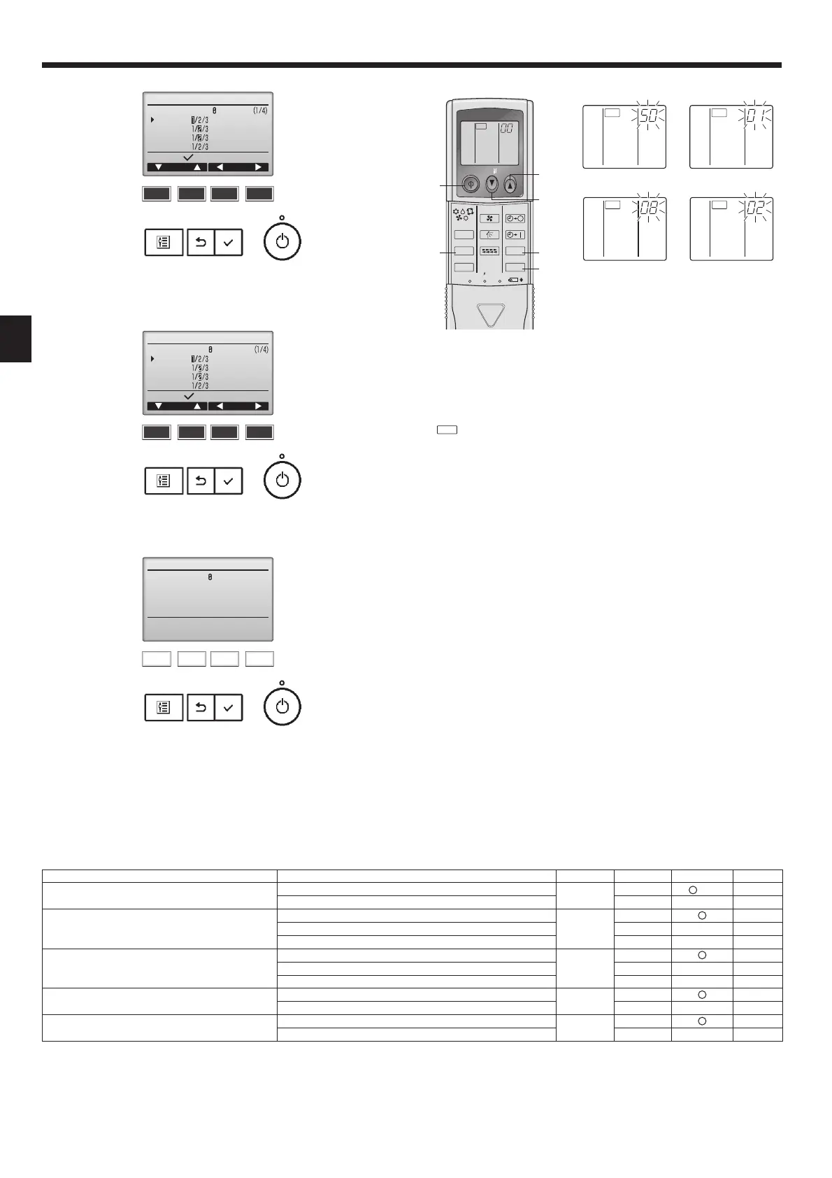
2) For wireless remote controller [Fig. 8-4-6]
③
① ②
CHECK CHECK
CHECKCHECK
④
ON/OFF TEMP
FAN
VANE
TEST RUN
AUTO STOP
AUTO START
h
min
LOUVER
MODE
CHECK
RESETSET CLOCK
CHECK
Ⓔ
Ⓕ
Ⓓ
Ⓒ
Ⓐ
Ⓑ
1. Changing the external static pressure setting.
• Be sure to change the external static pressure setting depending on the duct and
the grill used.
①
Go to the function select mode
Press the CHECK button
Ⓕ
twice continuously.
(Startthisoperationfromthestatusofremotecontrollerdisplayturnedo.)
is lighted and “00” blinks.
Press the TEMP button
Ⓒ
once to set “50”. Direct the wireless remote controller
toward the receiver of the indoor unit and press the Hour button
Ⓐ
.
②
Setting the unit number
Press the TEMP button
Ⓒ
and
Ⓓ
to set the unit number to 07. Direct the
wireless remote controller toward the receiver of the indoor unit and press the
Minute button
Ⓑ
.
③
Selecting a mode
Enter 08 to change the external static pressure setting using the
Ⓒ
and
Ⓓ
buttons.
Direct the wireless remote controller toward the receiver of the indoor unit and
press the Hour button
Ⓐ
.
Currentsettingnumber: 1=1beep(onesecond)
2=2beeps(onesecondeach)
3=3beeps(onesecondeach)
④
Selecting the setting number
Use the
Ⓒ
and
Ⓓ
buttons to change the external static pressure setting to be
used.
Direct the wireless remote controller toward the sensor of the indoor unit and
press the Hour button
Ⓐ
.
⑤
To set the external static pressure
Repeat steps
③
and
④
to set the mode number to 10.
⑥
Complete function selection
Direct the wireless remote controller toward the sensor of the indoor unit and
press the ON/OFF button
Ⓔ
.
Note:
• Whenever changes are made to the function settings after installation or
maintenance, be sure to record the changes with a mark in the “Check”
column of the Function table.
3) Changing the power voltage setting (Function table 1)
• Be sure to change the power voltage setting depending on the voltage used.
Ⓐ
Hour button
Ⓓ
TEMP button
Ⓑ
Minute button
Ⓔ
ON/OFF button
Ⓒ
TEMP button
Ⓕ
CHECK button
Function table 1
Select unit number 00
Mode Settings
Mode no. Setting no. Initial setting Check
Power failure automatic recovery*1
(AUTORESTARTFUNCTION)
Not available
01
1
(*1)
Available
2
Indoor temperature detecting
Indoor unit operating average
02
1
Set by indoor unit’s remote controller
2
Remote controller’s internal sensor
3
LOSSNAY connectivity
Not Supported
03
1
Supported(indoorunitisnotequippedwithoutdoor-airintake)
2
Supported(indoorunitisequippedwithoutdoor-airintake)
3
Power voltage
240V
04
1
220V, 230V
2
Auto mode
Energy saving cycle automatically enabled
05
1
Energy saving cycle automatically disabled
2

 Loading...