15
[Output pattern A] Errors detected by indoor unit
Wireless remote controller
Wired remote
controller
Symptom Remark
Beeper sounds/OPERATION
INDICATORlampashes
(Numberoftimes)
Check code
1 P1 Intake sensor error
2 P2, P9 Pipe(Liquidor2-phasepipe)sensorerror
3 E6, E7 Indoor/outdoor unit communication error
4 P4 Drain sensor error
5 P5 Drain pump error
6 P6 Freezing/Overheating safeguard operation
7 EE Communication error between indoor and outdoor units
8 P8 Pipe temperature error
9 E4 Remote controller signal receiving error
10 – –
11 PB Fan motor error
12 Fb Indoorunitcontrolsystemerror(memoryerror,etc.)
No sound – – No corresponding
[OutputpatternB]Errorsdetectedbyunitotherthanindoorunit(outdoorunit,etc.)
Wireless remote controller
Symptom Remark
Beeper sounds/OPERATION INDICATOR
lampashes(Numberoftimes)
1 Indoor/outdoorunitcommunicationerror(Transmittingerror)(Outdoorunit)
For details, check the LED
display of the outdoor controller
board.
2 Compressor overcurrent interruption
3 Open/short of outdoor unit thermistors
4 Compressorovercurrentinterruption(Whencompressorlocked)
5 Abnormalhighdischargingtemperature/49Cworked/insucientrefrigerant
6 Abnormalhighpressure(63Hworked)/Overheatingsafeguardoperation
7 Abnormal temperature of heat sink
8 Outdoor unit fan protection stop
9 Compressor overcurrent interruption/Abnormal of power module
10 Abnormality of super heat due to low discharge temperature
11
Abnormality such as overvoltage or voltage shortage and abnormal
synchronous signal to main circuit/Current sensor error
12 –
13 –
14 Othererrors(Refertothetechnicalmanualfortheoutdoorunit.)
*1 If the beeper does not sound again after the initial two beeps to conrm the self-check start signal was received and the OPERATION INDICATOR lamp does
not come on, there are no error records.
*2 If the beeper sounds three times continuously “beep, beep, beep (0.4 + 0.4 + 0.4 sec.)” after the initial two beeps to conrm the self-check start signal was
received, the specied refrigerant address is incorrect.
• On wireless remote controller
The continuous buzzer sounds from receiving section of indoor unit.
Blink of operation lamp
• On wired remote controller
Check code displayed on the LCD.
• CheckthatallLEDsonthetwocontrolboardsontheindoorunitarelitorblinking(3each,6total).
9. Test run
9.3. Test run
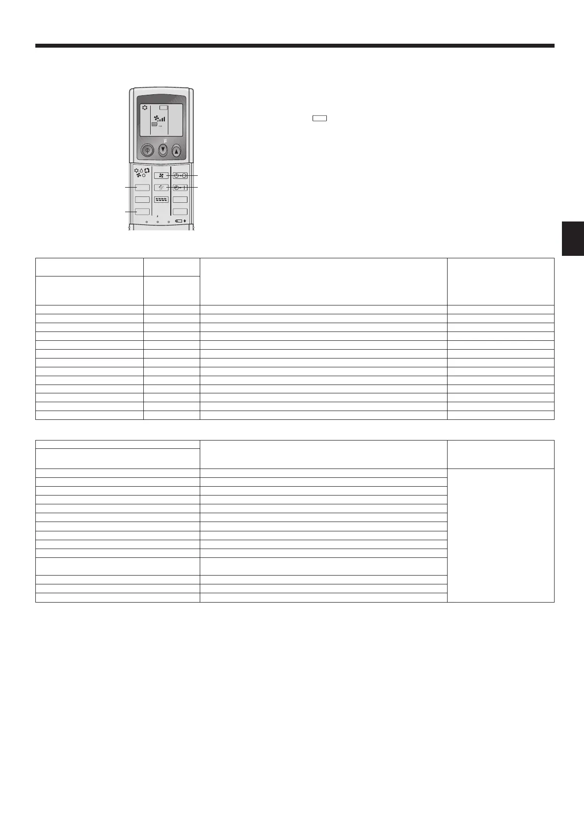
9.3.1. Using wireless remote controller (option)
[Fig. 9-3]
ON/OFF TEMP
FAN
VANE
TEST RUN
AUTO STOP
AUTO START
h
min
LOUVER
MODE
CHECK
RESETSET CLOCK
TEST RUN
Ⓑ
Ⓐ
Ⓒ
Ⓓ
Ⓐ
TEST RUN button
Ⓑ
MODE button
Ⓒ
FAN button
Ⓓ
VANE button
①
Turn on the power to the unit at least 12 hours before the test run.
②
Press the TEST RUN button
Ⓐ
twice continuously.
(Startthisoperationfromthestatusofremotecontrollerdisplayturnedo.)
and current operation mode are displayed.
③
Press the MODE button
Ⓑ
to activate COOL mode, then check whether cool
air is blown out from the unit.
④
Press the MODE button
Ⓑ
to activate HEAT mode, then check whether warm
air is blown out from the unit.
⑤
Press the FAN button
Ⓒ
and check whether fan speed changes.
⑥
Press the ON/OFF button to stop the test run.
Note:
• Point the remote controller towards the indoor unit receiver while
following steps
②
to
⑥
.
• It is not possible to run the in FAN, DRY or AUTO mode.

 Loading...