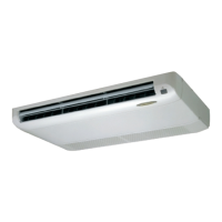
4-1. PURGING PROCEDURES AND LEAK TEST
Fig. 1 Fig. 2
Fig. 3 Fig. 4
Fig. 5 Fig. 6
3. FLARING WORK AND PIPE CONNECTION
3-1. FLARING WORK
Pipe diameter
(mm)
Nut
(mm)
A (mm) Tightening torque
Clutch
type tool
for
R410A
Clutch
type tool
for R22
Wing nut
type tool
for R22
N•m kgf•cm
ø6.35 (1/4”) 17
0 to 0.5 1.0 to 1.5
1.5 to 2.0
13.7 to 17.7 140 to 180
ø9.52 (3/8”) 22 34.3
to 41.2 350 to 420
ø12.7 (1/2”) 26
2.0
to 2.5
49.0 to 56.4 500 to 575
ø15.88 (5/8”) 29 73.5
to 78.4 750 to 800
Tilted Uneven Burred
Good
No good
Burr
Copper pipe
Spare reamer
Pipe cutter
Smooth all
around
Even
length
all around
Inside is shin-
ing
without any
scratches.
Flare nut
Die
Copper
pipe
Clutch type
Flaring tool
Wing nut type
3-2. PIPE CONNECTION
1) Apply a thin coat of refrigeration oil (G) to the ared ends of the pipes
and the pipe connections of the outdoor unit. Do not apply refrigeration
oil on screw threads. Excessive tightening torque will result in damage
on the screw.
2) Align the center of the pipe with that of the pipe connections of the out
-
door unit, then hand tighten the are nut 3 to 4 turns.
3)
Tighten the are nut with a torque wrench as specied in the table.
• Over-tightening may cause damage to the are nut, resulting in refrig-
erant
leakage.
• Be sure to wrap insulation around the piping. Direct contact with the
bare piping may result in burns or frostbite.
3-3. INSULATION AND TAPING
1) Cover piping joints with pipe cover.
2) For outdoor unit side, surely insulate every piping including valves.
3) Using piping tape (E), apply taping starting from the entry of outdoor
unit.
•
Stop the end of piping tape (E) with tape (with adhesive agent at-
tached).
•
When piping have to be arranged through above ceiling, closet or
where the temperature and humidity are high, wind additional commer-
cially
sold insulation to prevent condensation.
4. PURGING PROCEDURES, LEAK TEST, AND TEST RUN
Copper
pipe
1) Cut the copper pipe correctly with pipe cutter. (Fig. 1, 2)
2) Completely remove all burrs from the cut cross section of pipe. (Fig. 3)
• Aim the copper pipe downward while removing burrs to prevent
burrs from dropping in the pipe.
3) Remove are nuts attached to indoor and outdoor units, then put them
on pipe having completed burr removal. (Not possible to put them on
after aring work.)
4)
Flaring work (Fig. 4, 5). Firmly hold copper pipe in the dimension
shown in the table. Select A mm from the table according to the tool
selected.
5)
Check
• Compare the ared work with Fig. 6.
• If are is noted to be defective, cut off the ared section and do ar
-
ing
work again.
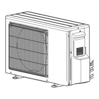
1) Remove service port cap of stop valve on the side of the outdoor unit
gas pipe. (The stop valves are fully closed and covered in caps in their
initial state.)
2) Connect gauge manifold valve and vacuum pump to service port of
stop valve on the gas pipe side of the outdoor unit.
3) Run the vacuum pump. (Vacuumize for more than 15 minutes.)
4) Check the vacuum with gauge manifold valve, then close gauge mani
-
fold
valve, and stop the vacuum pump.
5) Leave as it is for one or two minutes. Make sure the pointer of gauge
manifold valve remains in the same position. Conrm that pressure
gauge
shows -0.101 MPa [Gauge] (-760 mmHg).
6) Remove gauge manifold valve quickly from service port of stop valve.
7) Fully open all stop valves on the gas pipe and the liquid pipe. Operat-
ing
without fully opening lowers the performance and this causes trou-
ble.
8)
Refer to 1-2., and charge the prescribed amount of refrigerant if
needed. Be sure to charge slowly with liquid refrigerant. Otherwise,
composition of the refrigerant in the system may be changed and af-
fect
performance of the air conditioner.
9) Tighten cap of service port to obtain the initial status.
10
) Leak test
WARNING
When installing the unit, securely
connect the refrigerant pipes before
starting the compressor.
CAUTION
When there are the ports which are
not used, make sure their nuts are
tightened securely.
Service port cap
(Torque 13.7 to
17.7 N•m, 140 to
180 kgf•cm)
Stop
valve
for GAS
Stop valve cap
(Torque 19.6 to
29.4 N•m, 200
to 300 kgf•cm)
Gauge manifold
valve (for R410A)
Compound pressure
gauge (for R410A)
–0.101MPa
(–760
mmHg)
Handle
Low
Handle
High
Vacuum pump
(for R410A)
Charge hose
(for R410A)
*Close
*Open
Hexagonal
wrench
*4 to 5 turns
Stop valve
for LIQUID
Pressure gauge
(for R410A)
Precautions when using
the control valve
When attaching the control valve to
the service port, valve core may de-
form or loosen if excess pressure is
applied. This may cause gas leak.
Service port
Charge hose
(for R410A)
Body
Close
Open
Control
valve
A
When attaching the control valve to
the service port, make sure that the
valve core is in closed position, and
then tighten part A. Do not tighten
part A or turn the body when valve
core is in open position.
 Loading...