Removal steps
>>E<<
1. Crankshaft bearing cap bolt
>>E<<
2. Crankshaft bearing cap
>>D<<
3. Crankshaft bearing lower
<<A>>
4. Crankshaft
>>C<<
5. Crankshaft bearing upper
>>B<<
6. Thrust bearing
>>A<<
7. Crankshaft sensing ring
8. Cylinder block
CRANKSHAFT AND CYLINDER BLOCK
ENGINE OVERHAUL
11B-60
REMOVAL SERVICE POINT
<<A>> CRANKSHAFT REMOVAL
When temporarily placing the crankshaft with the
crankshaft sensing ring attached, temporarily place it
on a V-block to prevent teeth of the sensing ring from
deforming.
NOTE: If a tooth bends, be sure to replace the crank-
shaft sensing ring with a new one.
INSTALLATION SERVICE POINTS
>>A<< CRANKSHAFT SENSING RING
INSTALLATION
AKB00121
AC
1
2
3
Crankshaft sensing ring
Tighten crankshaft sensing ring bolts to the torque of
11
± 1 N⋅m in the tightening order shown in the illus-
tration.
>>B<< THRUST BEARING INSTALLATION
1. Install the thrust bearing on the No. 3 bearing on
the cylinder block side. Application of engine oil
makes the installation easy.
AK502394
Groove
AD
2. Install the thrust bearing so that the grooved side
is on the crankshaft weight side.
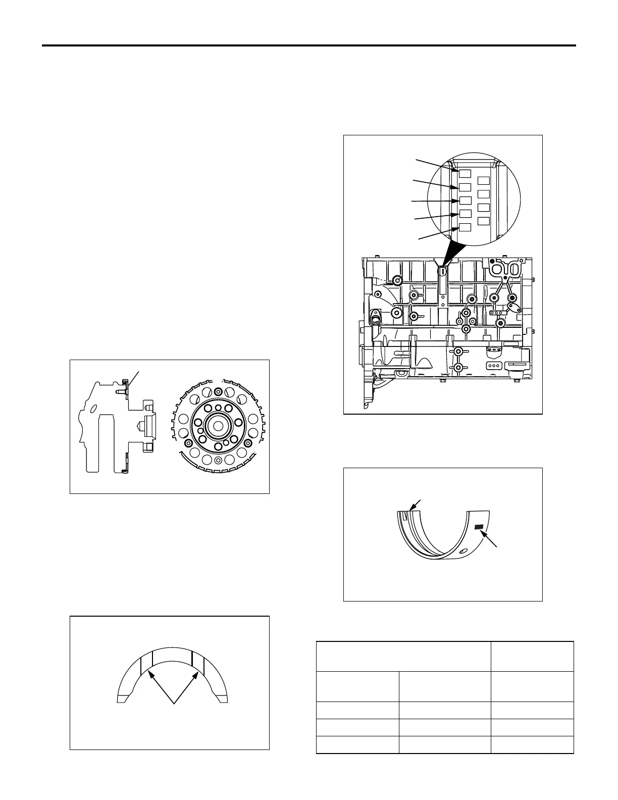
>>C<< CRANKSHAFT BEARING UPPER
INSTALLATION
J2
J3
J4
J5
J1
AK502530
No.1
No.2
No.3
No.4
No.5
AC
1. When replacing the crankshaft bearing upper,
select a bearing with the size corresponding to the
cylinder block journal diameter in the table below.
AK502396
Groove
AF
Identification
mark
2. The crankshaft bearing upper has an identification
mark at the illustrated position.
Cylinder block Crankshaft
bearing
Identification
mark
Journal
diameter mm
Identification
mark
1 56.000 − 56.006 1
2 56.006 − 56.012 2
3 56.012 − 56.018 3
3. Install the selected crankshaft bearing upper.

 Loading...