4 - 39 4 - 39
4 SFC PROGRAM CONFIGURATION
MELSEC-Q
POINT
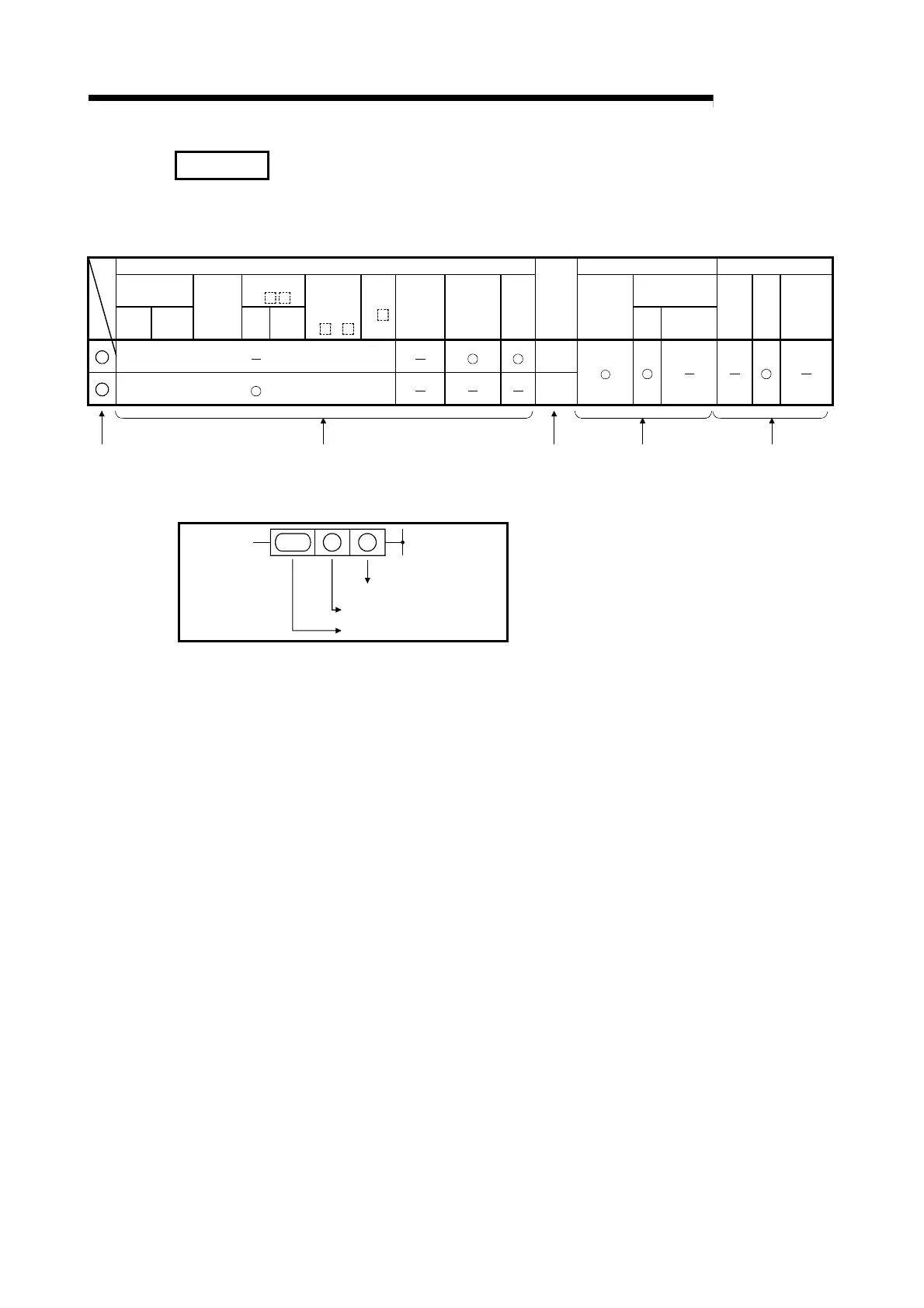
Beginning from Section 4.4.1 of this manual, the following table is used in the explanations of
the various instructions. The table contents are explained below.
Usable Devices Programs Using Instructions Execution Site
Internal Device
(System, User)
Link Direct
J
\
SFC Program
Bit Word
File
Register
R
Bit Word
Intelligent
Function
Module
U
\G
Index
Z
Constant
K, H
Expansion
SFC
BLm\Sn
Other
Data
Type
Sequence
Program
Step
Transition
Condition
Block Step
Transition
Condition
S
BIN16/
BIN32
D
BIN16/
BIN32
4)2) 5)1) 3)
1) Ladder symbols are indicated in this area.
MOV DS
Destination
Source
Instruction code
Destination ...................................Data destination following the operation.
Source ..........................................Where data is stored prior to the operation.
2) Usable devices are indicated at this area.
• Devices indicated by a circle mark (O) can be used with the instruction in question.
The device application classifications are shown below.

 Loading...


