11 - 12 11 - 12
MELSEC-Q
11 TROUBLESHOOTING
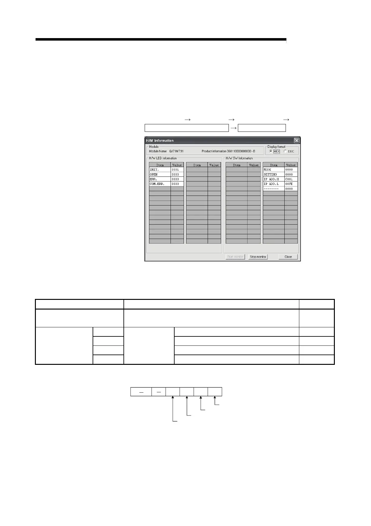
(b) When confirming the LED status and switch setting status on the H/W
Information screen of the diagnostics function
The H/W Information screen can be confirmed on GX Developer 8.29F or
later.
[Starting Procedure]
GX Developer
[Diagnostics] [System monitor]
Module's Detailed Information
H/W Information
[Display Data]
The QJ71MT91 data stored in the following buffer memory areas are
displayed.
Display Data Corresponding Buffer Memory Area Address
Left side of H/W LED Information
(*1) (*2)
Module status: LED status (*1) (*2) (*3) 0C05H(3077)
MODE Switch 1: Operation mode setting status 0C00H(3072)
SETTING Switch 2: Communication condition setting status 0C01H(3073)
IP ADD.H Switch 3: Local station IP address setting status 0C02H(3074)
Right side of H/W SW
Information
IP ADD.L
Intelligent function
module switch (*4)
Switch 4: Local station IP address setting status 0C03
H(3075)
*1: LED status structure
INIT.LED
OPEN LED
ERR.LED
COM.ERR.LED
b15
b5
to
b4 b3 b2 b1 b0
1/0 1/0 1/0 1/0
1: On
0: Off
*2: Refer to Section 11.1 for troubleshooting of the H/W LED.
*3: Refer to Section 11.4 for how to turn off the COM. ERR. LED.
*4: Refer to Section 6.6 for details of the intelligent function module switches.
 Loading...


