INTERFACE GUIDES
Have you got your interface cable already? If not, the next few pages provide a guide
to:
• 2 wire test interfacing
• 4 wire test interfacing
• Interface and connector guides
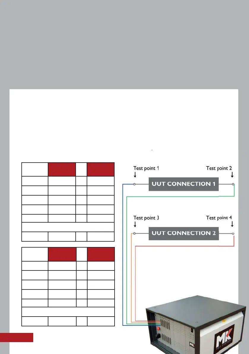
2 WIRE TEST INTERFACING
With 2 wire testing, the system will measure the resistance of the interface cable plus
the UUT (unit under test). You can offset the resistance of the interface cable using
the offset column in the netlist in MKAT Editor.
Note: Each pin on the test system is an individual test point.
6
TOP D
TEST
POINT
PIN 1 = 1
PIN 2 = 2
PIN 3 = 3
PIN 4 = 4
PIN 5 = 5
and so on...
PIN 32 = 32
BOTTOM
D
TEST
POINT
PIN 1 = 33
PIN 2 = 34
PIN 3 = 35
PIN 4 = 36
PIN 5 = 37
and so on...
PIN 32 = 64
Each pin on the test system is an individual test point.