Star density may be increased at a later date. Create even density in the constellation up
to the boundary, avoiding congestion. Sensors have a 120- degree eld of view, hence,
stars placed further than the tracking area remain benecial. Avoid mounting behind
cables or alongside structures where stars may become obscured. Stars may be mounted
at an angle or on walls if necessary.
If you put stars onto scaolding poles or lighting trusses, only stick middle of stars and
keep two “wings” on the side to increase the star surface seen by the sensor.
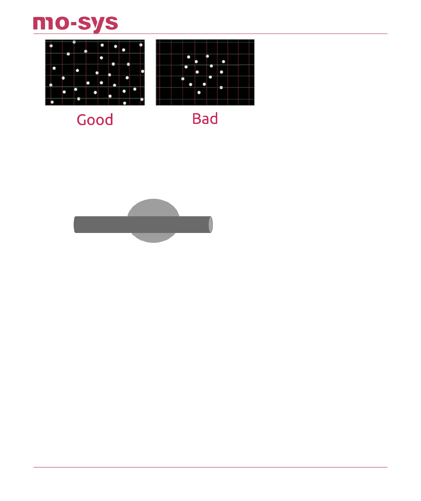
Summary
Fixed: mounted on permanent structures
Placed as randomly as possibly
Diering heights: placed on at least two levels
Well separated: spaced apart not clustered
Clearly visible: without cables hiding stars
Approximately 30 stars in the tracking image, minimum is 14
Good distribution through sensor camera eld of view
2.2 Star Installation Examples
An example of a 5-metre-high ceiling. The stars are positioned randomly with ideal spacing
across the ceiling and lighting grid. The reective metal surfaces do not present a problem for
the StarTracker sensor.
•
•
•
•
•
•
•
•
•
StarTracker Max Manual
2023 - 2024 © Mo-Sys Engineering Ltd. All rights reserved 4 of 70