Setup
7
04/99 AWB 27-1184 GB
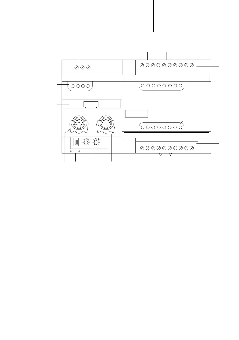
Figure 1: Overview of the PS4-200
24 V DC power supply
High-speed counter input (alternative to I 0.0), 3 kHz
Alarm input (alternative to I 0.1)
8 digital inputs 24 V DC and 24 V DC input for the
outputs
Plug-in screw terminal
Status LEDs for digital inputs
Status LEDs for digital outputs
6 digital outputs 24 V DC/0.5 A;
short-circuit and overload proof
2 analog inputs U
0
, U
1
(0 to 10 V)
1 analog output U
10
(0 to 10 V)
Suconet K interface
Setpoint potentiometers P1, P2
Switch S1 for bus terminating resistors
Programming device interface (PRG)
Memory module
Status LEDs for the PLC
S1
Power Supply
24V 0V
1=Ready
2=Run
3=Not Ready
4=Battery
Suconet K
1 2
1 2 3 4
Digital
Input
Digital
Output
Analog
Input/Output
PS4-201-MM1
.0
Output
Power Supply
.1 .2 .3 .4 .5
.0 .1 .2 .3 .4 .5 U
0
U
1
U
10
0V
A
.6 .7 24V
Q
0V
Q
햲
햳햵
햸
햹햻햽햺
햴
PRG
햷
햶
햶
헀
P1 P2
햾
햿
 Loading...

