Engineering
20
04/99 AWB 27-1184 GB
Suconet K interface Connector pin assignments
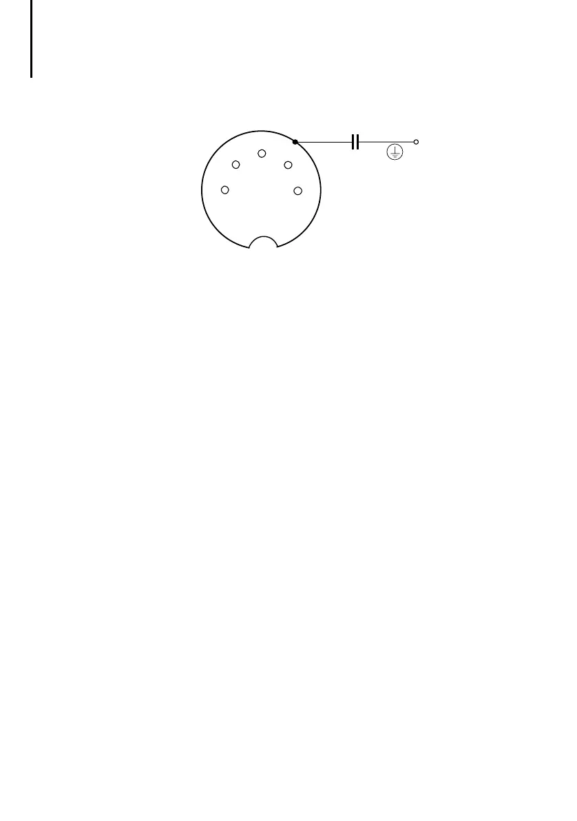
Figure 8: Pin assignment of the Suconet K interface (PRG)
(right-hand socket, top view)
The housing of the socket is connected to the ground
terminal of the PS4-200 power supply via a capacitor
(only applies to version 03 and earlier).
PIN 1 RS 485 data cable, Suconet K (TB/RB)
PIN 2 Assigned internally
PIN 3 Assigned internally
PIN 4 RS 485 data cable, Suconet K (TA/RA)
PIN 5 Assigned internally
Connecting to the Suconet K field bus
왘 Use the bus cable KPG 1-PS3 to connect
additional Suconet K stations (PS4, EM4) to the
compact PLC.
5-pole DIN plug 5-pole DIN plug
(pins) (pins)
1--------------------------------1
4--------------------------------4
왘 Connect the screen of the Suconet K data cable
both to the potential reference surface and to the
housing of the plug connector (see Fig. 4 “Screen
connection to reference potential surface”).
 Loading...
