Setting the bus terminating
resistors
21
04/99 AWB 27-1184 GB
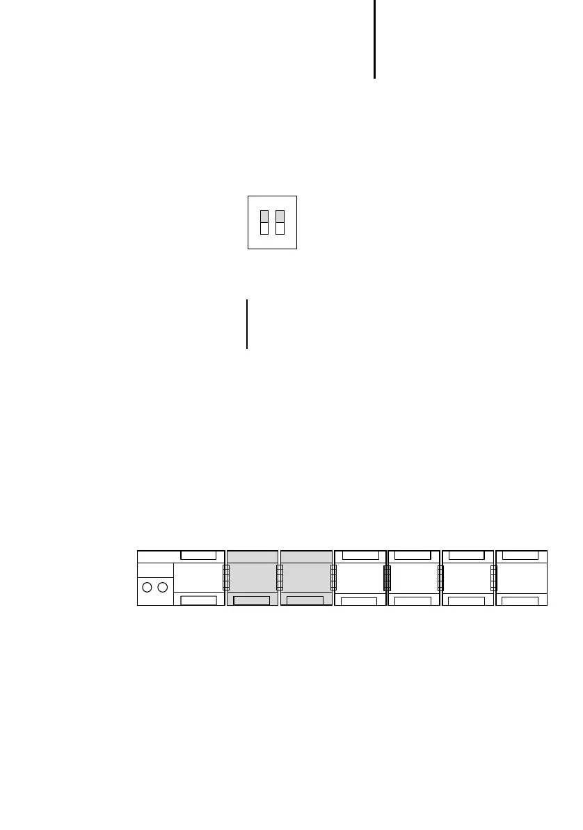
Setting the bus
terminating resistors
왘 Set the bus terminating resistors on the module
for the first and last physical stations on a line. To
do this, both S1 switches should be set to the
“ON” position. Both switches must be set to the
“OFF” position for all other stations.
Figure 9: Bus terminating resistors active
Local expansion The PS4-200 can be expanded locally. The local
expansion modules (LE4 modules) are connected to
the local bus connector of the PS4-200 using a local
bus ribbon cable. Up to six LEs can be connected
locally. All available LE types can be used. Up to two
of the LE4 shown in the legend under
can be
connected to a local line. They must only be
connected directly adjacent to the master (from
version 05).
LE4-206-AA1, LE4-622-CX1, LE4-501-BS1,
LE4-503-BS1, LE4-505-BS1
21
OFF
In order for the PLC to function correctly the two
S1 switches must be set to the same position
(“ON” or “OFF”).
햲햲
LE 4-... LE 4-... LE 4-... LE 4-...
PS 4-201-
MM1
 Loading...

