03/05 AWB2724-1453GB
Addressing inputs/outputs and
marker
43
Addressing inputs/outputs and marker
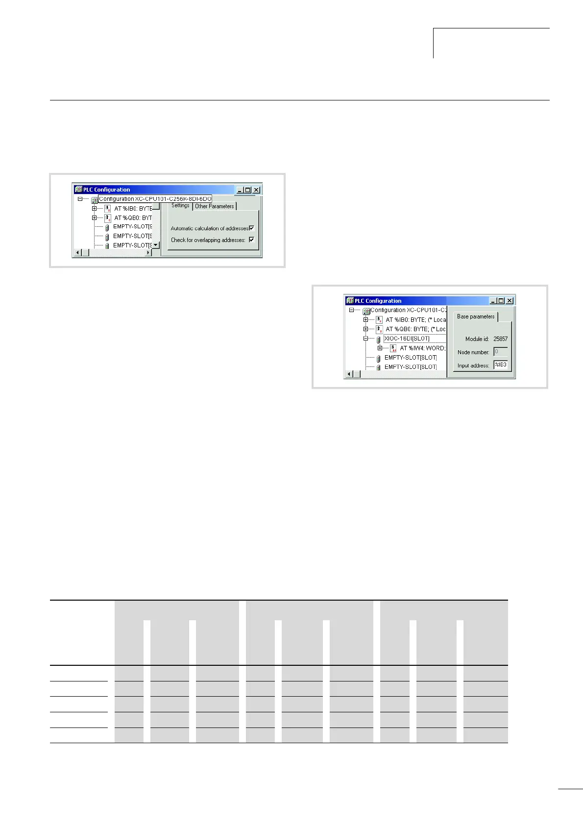
If you open the PLC configuration of a new project, you will receive
the current view of the default settings of the addressing. In this
setting the addresses are automatically assigned and address
conflicts (overlaps) are reported
If you add a module to the PLC in the configurator, the
configurator will assign this module with an address. Further
modules are assigned with the next addresses in ascending order.
You can also assign the addresses freely. However, if you access
the “Automatic calculation of addresses” function later, the
addresses are shown in reassigned ascending order.
“Activate Automatic addresses”
The addresses are automatically assigned or modified if a module
is changed or added. This can occur with a centrally assigned
module as well as a module which is a component of a decentral
PROFIBUS-DP slave or CAN station.
If you add a module, the addresses of all the subsequent modules
(independently of the line) are offset by the address value of the
added module, and the added module is assigned with an address.
Modules which are located in the configuration before the added
module are not changed. If you remove the tick in the “Automatic
calculation of addresses” checkbox, the addresses remain
unchanged with modifications/expansions.
“Activating Check for overlapping addresses”
If the check for overlapping addresses is activated, addresses
which are assigned twice will be detected and an error message is
generated during compilation. This setting should not be modified.
Uneven word addresses
(Independent of the “Check for overlapping addresses” setting)
If you assign an uneven offset address to a word addressable
module in the “Input address” field, e.g. IB3, the following even
word address (IW4) will automatically appear in the PLC
configurator.
Address range
Addresses can only be assigned within the valid ranges. The range
details can be found under ‹Target Settings l Memory Layout l
Size›.
The addresses are checked during compilation. It is essential to
ensure that the addresses of the configured module are used
(referenced) in the program. If the address exceeds the range, a
fault is signalled.
Table 10: Address ranges
Figure 55: Default setting of the addressing
Figure 56: Uneven address
PLC Input Output markers
Size Max.
Byte
address
Max.
Word
address
Size Max.
Byte
address
Max.
Word
address
Size Max.
Byte
address
Max.
Word
address
XC100-64k 2k 2047 2046 2k 2047 2046 4k 4095 4094
XC100-128k 4k 4095 4094 4k 4095 4094 8k 8191 8190
XC100-256k 16k 16383 16382 16k 16383 16382 16k 16383 16382
XC200-256k 4k 4095 4094 4k 4095 4094 16k 16383 16382
XC200-512k 4k 4095 4094 4k 4095 4094 16k 16383 16382

 Loading...
