Engineering
03/05 AWB2724-1453GB
18
Lightning protection
External lightning protection
All cables that go outside buildings must be shielded. Metal
conduit is the best solution to this problem. For signal cables, use
overvoltage protection devices, such as Varistors or other similar
devices. Install the protection devices as close as possible to the
cable entry into the building, at the latest there were the cable
enters the switchgear cabinet.
Internal lightning protection
Internal lightning protection covers all those measures taken to
reduce the effects of a lightning strike and the resulting electrical
and magnetic fields on metallic installation and electrical plant.
These measures are:
• equipotential bonding/earthing
• shielding
• using overvoltage protection devices.
Please consult the following manuals for advice on cable routing
and shielding measures:
• AWB27-1287 “EMC Project Engineering for Automation
Systems”.
• TB27-001-GB “Electromagnetic Compatibility (EMC) for
Automation systems”.
• TB02-022-GB “Electromagnetic Compatibility (EMC) for
Machinery and Plant”.
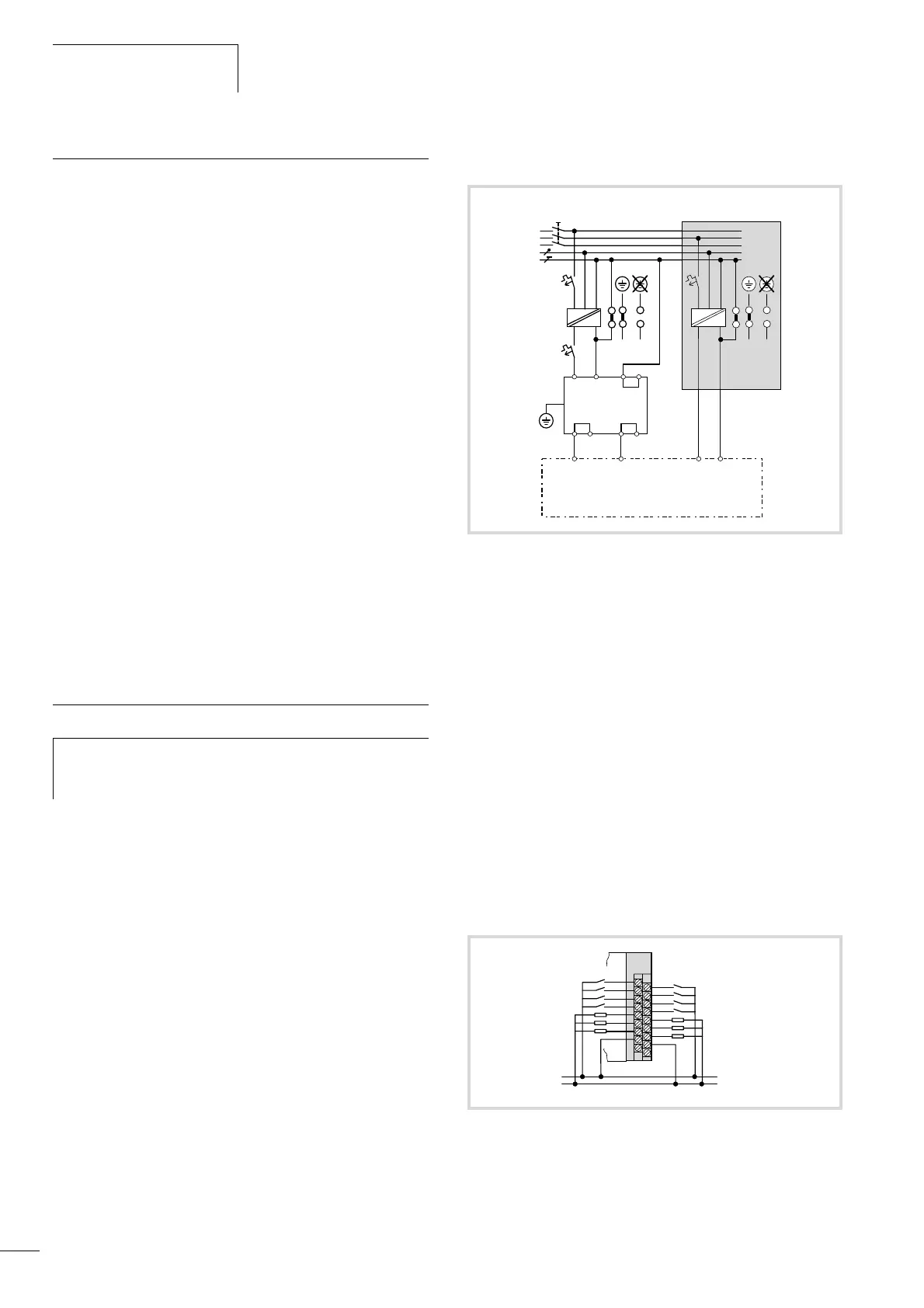
Wiring example
PSU
Power supply of the digital inputs/outputs
The wiring example indicates the wiring of a separate voltage
supply for inputs/outputs.
h
You can find wiring examples for the XI/OC modules in
the manual “Hardware and Engineering, XI/OC signal
Modules” (AWB2725-1452GB).
Figure 18: Wiring example for the supply section
a Main switch
b Protective cut-out
c 24 V DC supply voltage
d Earthed operation
e In floating (i.e. unearthed) operation, an isolation monitor must be
used (IEC 204-1, EN 60204-1, DIN EN 60204-1)
f 24 V DC line filter; ensures that a current of up to 2.2 A (maximum)
is available at a rated voltage of 24 V DC. Ensures that the EMC
stipulations for devices are fulfilled when the filter is used. The filter
is not a component of the CPU and must therefore be ordered
separately:
Type: XT-FIL-1
, Article no.: 285316 (Supplier: Moeller GmbH)
a „Dimensions“on page 72
a „Technical data“on page 76
1*) Internal jumper
2*) Additional PE connection via contact spring on rear
Figure 19: Example for wiring the terminal block
~
=
~
=
a
ed
f
ed
c
b
L1
L2
L3
N
PE
24 V
0 V DC 24 V
Q
0 V
Q
DC
XC-CPU101-CxxK-8DI-6DO
1*)
1*)1*)
XT-FIL-1
2*)
(Voltage supply of CPU101) (Voltage supply of the
local digital inputs/outputs)
+ 24 V
Q
H
0 V
Q
H
0
2
4
6
0
2
4
1
3
5
7
1
3
5

 Loading...
