03/05 AWB2724-1453GB
19
3 CPU operation
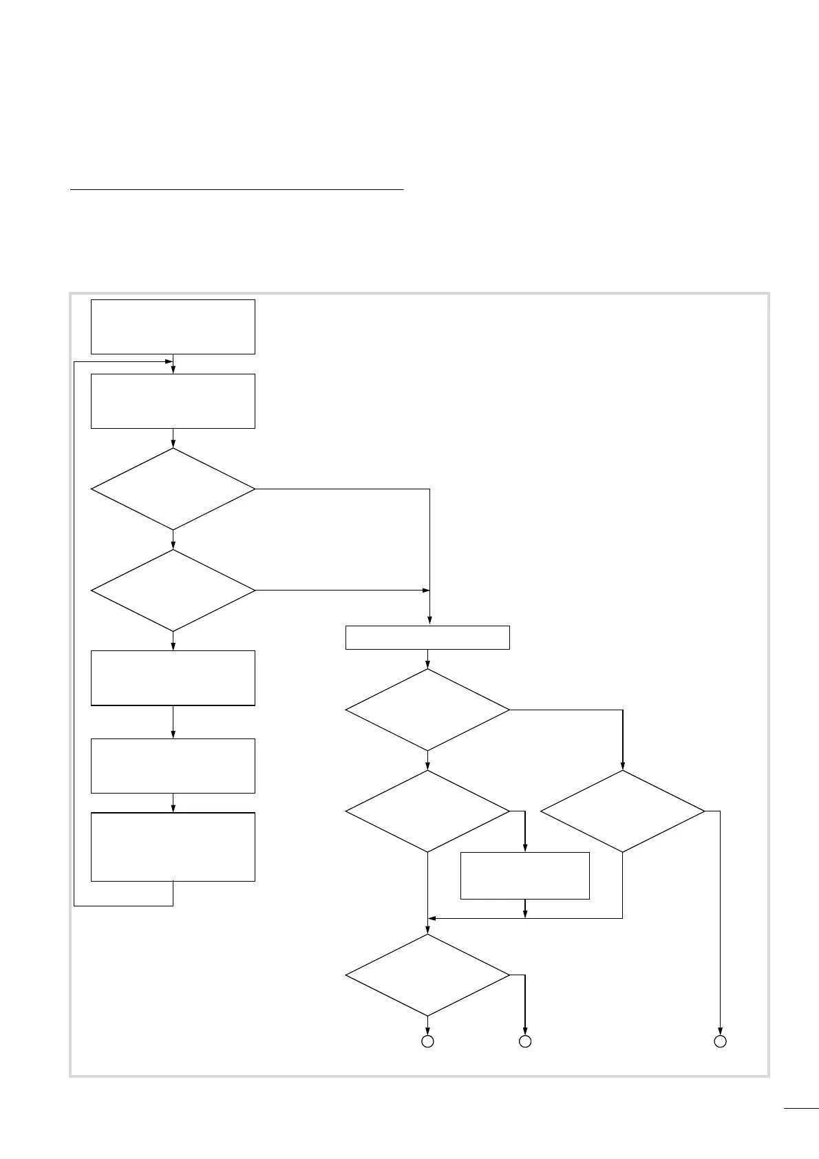
Switch-on behaviour
After the supply voltage is switched on the CPU will carry out a
self-test and several CRC checks. If a fault is detected, it will
remain in the “Switch-on not OK” state, a chapter “Operating
states” on page 41. After the tests have been successfully
completed, the operating system (OS) takes over the
communication with the XSoft programming system as well as
execution and debugging of the application program. It only
supports one application program.
Figure 20: Switch-on behaviour
OS MMC k OS PLC?
OS in MMC?
Power on
Yes
No
Yes
No
PLC Start
OS MMC a PLC
Application will be deleted
Default settings:
38.4 KB COM1
125 KB CAN
127 CAN Node ID
Boot project MCC
=
Main memory project
(SRAM)
Boot project
in
MCC
CPU start
Load project in main
memory (SRAM),
prepare cold start
RUN/STOP switch
in
RUN
Yes
Yes
NOT READY
Executable
project in
main memory
(SRAM)
No
Yes
READYRUN
No
No
Yes
No
 Loading...

