Program processing and
system time
03/05 AWB2724-1453GB
30
Functions
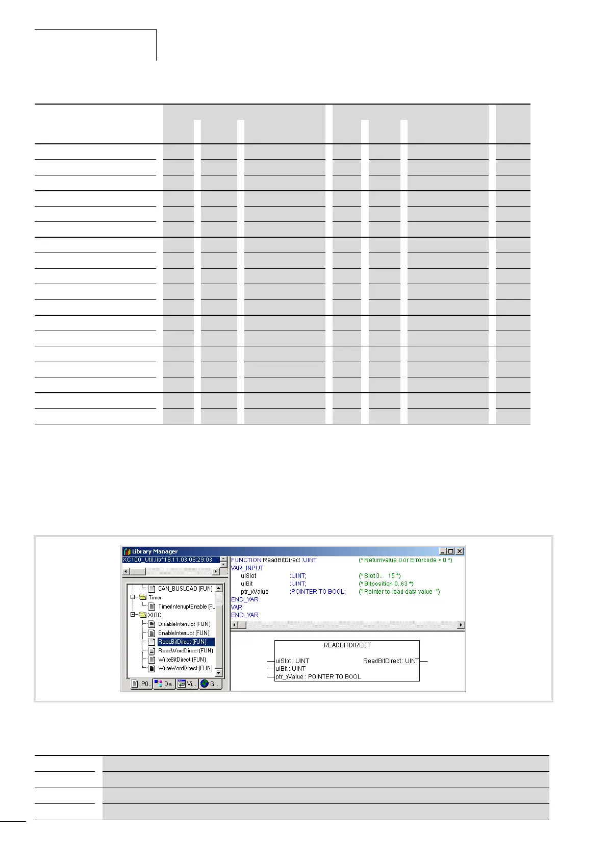
ReadBitDirect
A bit of an input module can be read directly with this function.
The state of an input bit is stored in the variables, which indicate
to the parameterized pointer “ptr_xValue”. The pointer variable
will not be changed when a fault occurs during processing.
Table 5: Parameters of the “ReadBitDirect” function
XIOC-16DO-S
– j 0 to 15 – j 0 1 to 15
XIOC-12DO-R
– j 0 to 11 – j 0 1 to 15
XIOC-16DX
– j 0 to 15 j j 0 1 to 15
XIOC-8AI-I2
– – – j – 0 to 7 1 to 15
XIOC-8AI-U1 – – – j – 0 to 7 1 to 15
XIOC-8AI-U2
– – – j – 0 to 7 1 to 15
XIOC-4T-PT
– – – j – 0 to 3 1 to 15
XIOC-2AO-U1-2AO-I2
– – – – j 0 to 3 1 to 15
XIOC-4AO-U1
– – – – j 0 to 3 1 to 15
XIOC-4AO-U2 – – – – j 0 to 3 1 to 15
XIOC-2AO-U2
– – – – j 0 to 1 1 to 15
XIOC-4AI-2AO-U1
– – – j j AI: 0 to 3, AO: 0 to 1 1 to 15
XIOC-2AI-1AO-U1
– – – j j AI: 0 to 1, AO: 0 1 to 15
XIOC-1CNT-100KHZ
– – – – – – 1 to 15
XIOC-2CNT-100KHZ
– – – – – – 1 to 15
XIOC-2CNT-2AO-INC – – – j j 1 to 15
XIOC-SER
– – – – – COM2, COM3 1 to 15
XIOC-NET-DP-M
– – – – – – 1 to 3
Modules I/O bit access I/O word access I/O slot
Read Write Param./Module Read Write Param./Module Param.
Figure 40: ReadBitDirect function
uiSlot: Slot number of the signal module. For possible parameters see table 4 on page 29
uiBit:
Bit position within the input value of the signal module. For possible parameters see table 4 on page 29
ptr_xValue: Pointer to the variable value
ReadBitDirect: Display of the fault code, see table 9 on page 33
 Loading...

