-43-
Revision 2/F3506
APPENDIX A. POWER RELAY UPGRADE KIT
Power switch
Mini-contactor
Kit Includes
1 x Power relay
2 x Screw - 8 x
3
/
8
truss
1 x 160mm black wire
1 x 180mm red wire
1 x 950mm red wire
1 x 1050 red wire
Assembly Instructions: (THE ELECTRICAL SUPPLY MUST BE DISCONNECTED)
1) Remove the rear service panel.
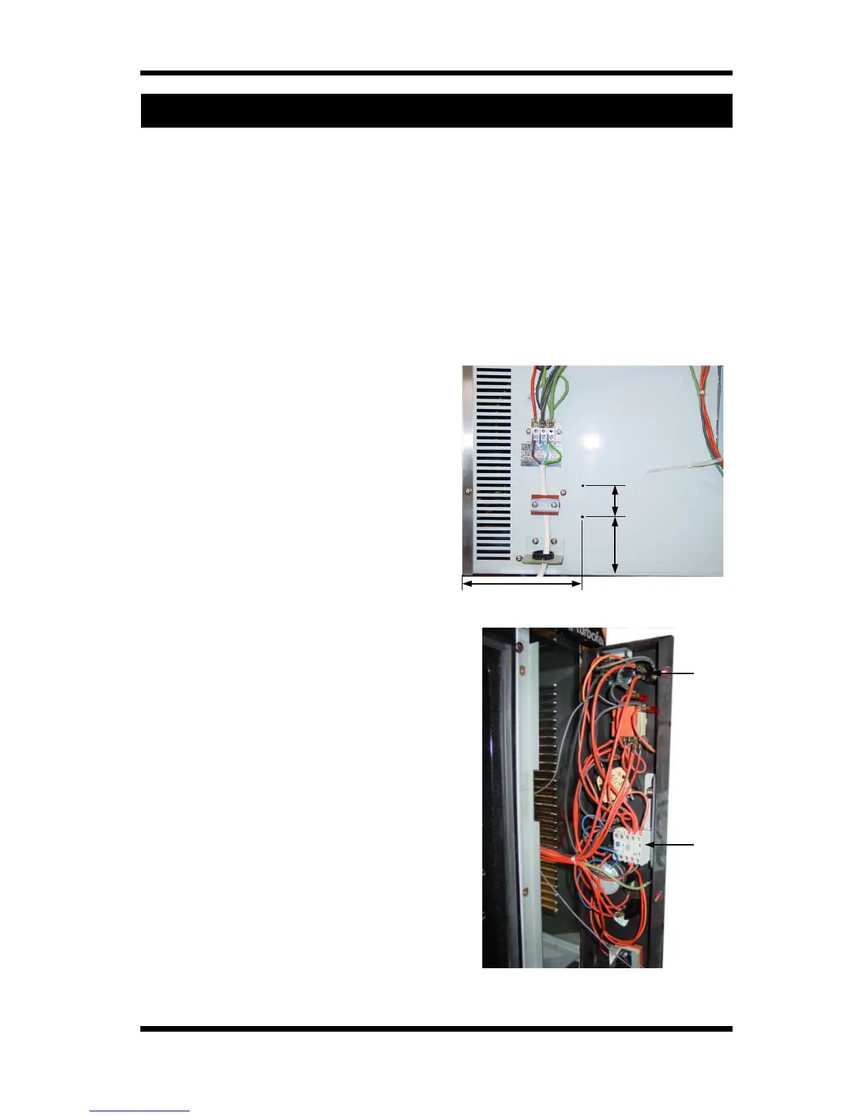
2) Mark and drill 2x ø3.5mm holes as per
figure A.1.
3) Mount relay to holes with 2 screws
provided.
(NOTE: Terminals on relay must face
upwards).
4) Connect 160mm black wire to vacant
neutral (L2) terminal on terminal block and
to terminal B on relay.
5) Connect short (180mm) red wire to vacant
phase (L1) terminal on terminal block and
to terminal 7 on relay.
6) Connect long thick red wire (950mm) to
power relay terminal 4 and remaining long
thin wire (1050mm) to relay terminal A.
Feed these wires through the plastic bush
in the rear of the oven and into the control
cavity.
7) Loosen screws and open the control panel.
8) Units with mini-contactor:
Remove and discard wire from terminal 2
on the power switch to terminal 21 on the
mini contactor inside the control panel.
Locate end of thick red wire previously fed
into control cavity and connect to terminal
21 of the contactor.
Units with ‘Schrack’ relay:
Remove and discard wire from terminal 2
on the power switch to terminal 7 on the
‘Schrack’ relay inside the control panel.
Locate end of thick red wire previously fed
into control cavity and connect to terminal 7
of the ‘Schrack’ relay.
9) Locate long thin red wire and connect to
terminal 2 on the power switch.
10) Close and fasten control panel taking care
not to trap any wires.
11) Replace and fasten rear service panel.
Figure A.1
Figure A.2
64
85
185