Revision 3/F3563
© Moffat Ltd, August 2006 E27 Convection Oven
-16-
Fan motor timer faulty
With oven switched on, and door closed,
ensure that the cams on the motor timer are
rotating.
6.1 FAULT DIAGNOSIS
Incorrect electrical supply
Check that the voltage across phase and
neutral (L1 and L2) terminals of terminal block
is the voltage as stated on the unit’s electrical
rating plate.
If incorrect, check electrical connection of
supply wiring and / or check electrical supply.
6.1.1 OVEN DOES NOT OPERATE / START
Power switch faulty
Check if power switch latches. If the switch
does not latch, then switch is faulty—replace.
With switch latched, check voltage across
terminal one to terminal three or four. If there
is no voltage, check for fault in wiring.
Check voltage across terminal two to terminal
three or four. If there is no voltage, then
switch is faulty—replace.
NOTE:
When power switch is latched, it
should illuminate if operating
correctly.
6.1.2 FAN DOESN’T OPERATE
Microswitch out of adjustment
Open oven door and manually depress door
microswitch actuator at top right of oven. If
this activates the fan, then the microswitch
actuator arm inside control cavity requires
adjustment.
Microswitch faulty
Check voltage from microswitch terminals to
neutral.
With the door closed there should be power to
the com terminal and the n.o. terminal.
With the door open there should be power to
the com terminal and the n.c. terminal.
If not, microswitch is faulty—replace.
Microswitch
n.o.
com
n.c.
Figure 6.1.1
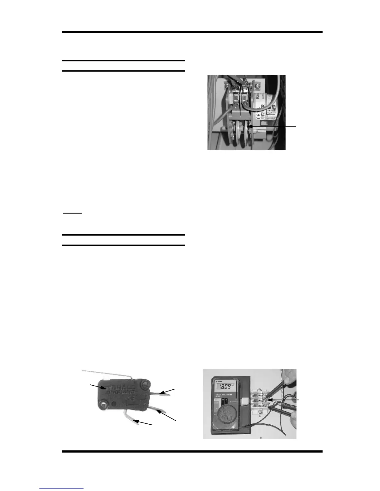
Fan motor capacitor faulty
Ensure that oven is isolated from the power
supply. Disconnect all wires from the motor
terminal block, except for the two capacitor
wires. Briefly short across the capacitor
terminals, to ensure that it is fully discharged.
Using a multimeter, measure the resistance
across capacitor terminals.
Figure 6.1.3
If cams are rotating, then isolate the power
supply from the oven. Remove the bottom
wire from the left hand switch terminals.
Rotate the cams manually whilst testing for
continuity through the left hand switch. Check
that the continuity cycles as the cams are
rotated. Re-secure the left hand wire, and
then repeat test for right hand switch.
When operating, 50Hz models should cycle
the power for approximately 80 seconds
through each switch, with a 10 second delay
between each cycle.
On 60Hz models the power should cycle
for approximately 65 seconds through each
switch, with an 8 second delay between each
cycle.
If there is no continuity, or the continuity does
not cycle correctly then timer is faulty -
replace.
Figure 6.1.2
Motor
Cams
(Rotate one
revolution every
3 minutes)
Capacitor
Terminals