– 47 –
STEP COMPONENT TEST LOCATIONS EXPECTED VOLTAGE
1 Lock Motor - Lock N to J8 pin 1 (gray) 120 VAC**
1 Vent Fan N to J8 pin 6 (orange) 120 VAC
1 Inner Broil Element* L2 to J6 240 VAC
1 Outer Broil Element* L2 to J2 240 VAC
2 Lock Motor - Unlock N to J8 pin 1 (gray) 120 VAC**
3 Convection Fan CCW N to J8 pin 8 (blue) 120 VAC
5 Convection Fan CW N to J8 pin 7 (red/white) 120 VAC
5 Inner Convection Element L2 to J4 240 VAC
5 Outer Convection Element L2 to J10 240 VAC
7 Cooling Fan - High Speed N to J8 pin 3 (black) 120 VAC
7 Inner Bake Element L2 to J5 240 VAC
7 Outer Bake Element L2 to J3 240 VAC
9 Cooling Fan - Low Speed N to J8 pin 5 (red) 120 VAC
* Step #1 or Step #3 will test these components.
** 120 VAC only present during the fi rst 10 seconds of test.
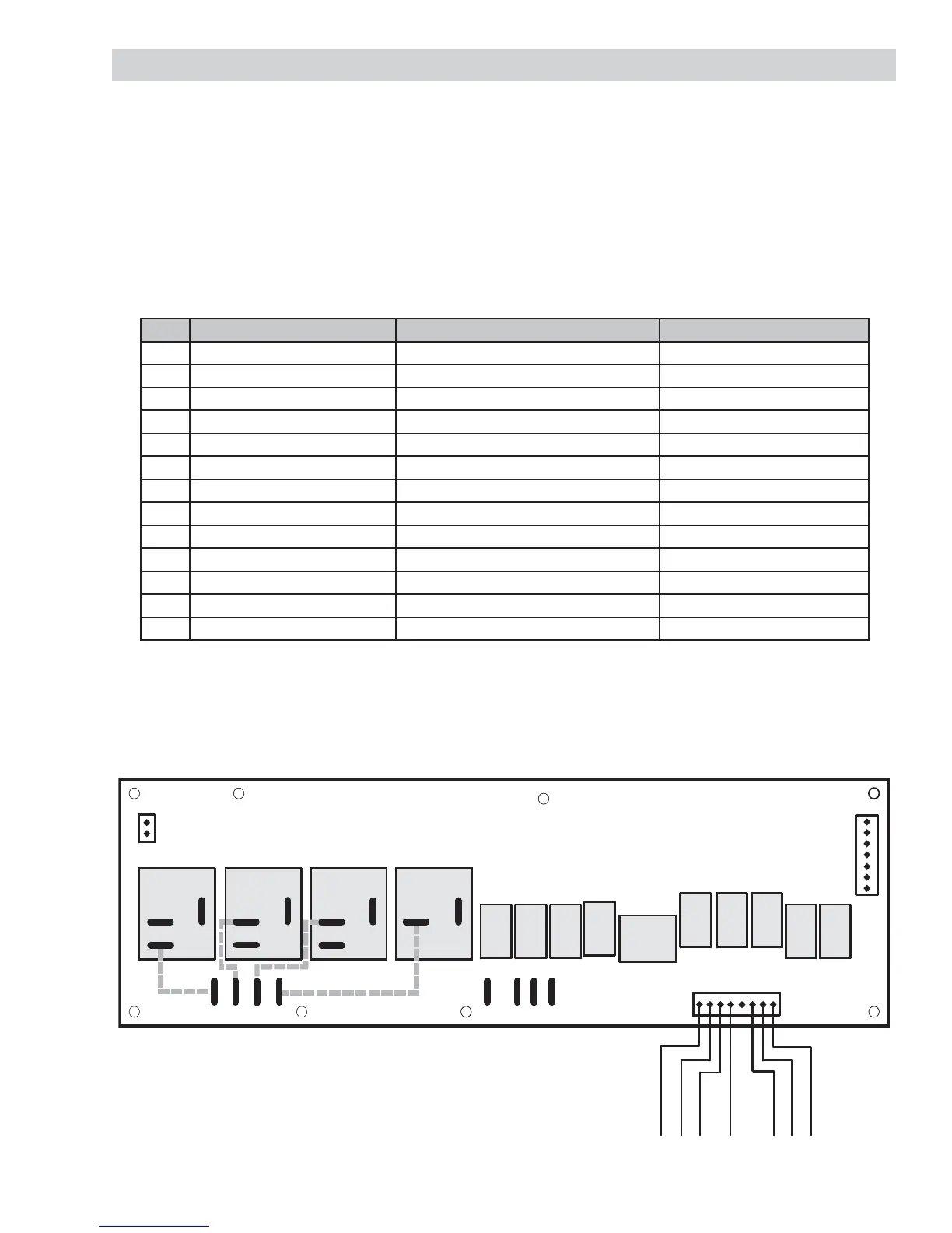
Component Voltage Test
The voltage applied to certain components can be tested individually. Enter the Service Test Mode and
select the step for the operation of the desired component. Check for proper voltage on the relay board as
described in the table and shown on the diagram below.
Note:
N (Neutral) can be measured from the J7 terminal on the relay board or from the U12 connector on the
Power Supply board.
L2 can be measured from the orange wire on the common terminal C of the Double Line Break relay or
on the black wire at the 240 VAC power harness.
•
•
Test Location Diagram
J7 J6 J5 J10 J11 J2J3 J4
K3
K16 K18
K1
K2 K8
K13
K6
K5 K14
K10
K4
K9
J8
1
J12
1
J9
K17
Double Line
Break Relay
Inner Broil
Relay
Inner Bake
Relay
Outer Convection
Relay
Outer
Broil
Relay
Outer
Bake
Relay
Inner
Convection
Relay
Convection
Fan
Relay
Convection
Fan
Directional
Relay
Vent
Fan
Relay
Low
Speed
Cooling
Fan
Relay
Oven
Light
Relay
High
Speed
Cooling
Fan
Relay
Lock
Motor
Relay
NC
NO
C
Black
Gray
Brown
Blue
Red/White
NC
NO
C
NC
NO
C
NO
C
Orange
Red
8
3
2
45
6
7