11
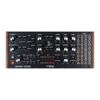
The core of Labyrinth is its dual generative sequencer. Each sequencer (SEQ1, SEQ2) consists of eight
bits—each of which can be either on (LED red) or o (LED o). They are clocked by the internal clock
set by TEMPO by default. Each sequencer additionally has its own 3.5mm CLOCK input for external
clocking, and each will respond to MIDI clock as well.
As the play head (represented by a green LED) of the sequencer runs through the sequence, a
trigger is output whenever the current bit is on (LED red). When the play head reaches the end of the
sequencer it loops back to the beginning, making each SEQ a basic eight-step sequencer. The LENGTH
of either sequencer can be set to any length from 1 to 8 by pressing its respective LENGTH button until
the desired length is achieved, and each sequencer’s sequence can be rotated by one bit to the right
via the BIT SHIFT button. Additionally, both SEQs may be chained together using CHAIN SEQ to form
a single sequence of up to 16 steps.
Travelling in sync with the play head is the write head (indicated by a red LED flashing in time with the
incoming clock). Pressing BIT FLIP on the current bit location of the write head will flip that bit either
on or o. When a bit is flipped on, a random voltage value between –5V and +5V is generated and
stored in that bit location. By flipping bits on, a random sequence of voltages is generated in each SEQ
which can be used to control the VCO, MOD VCO, VCW FOLD, and VCF CUTOFF to create generative
patterns.
NOTE: The play head and write head by default are at the same position. For advanced sequencer operation,
you may oset the write head from the play head via the BIT SHIFT + ADVANCE button combination—see the
“Sequencer Button Combos” table on page 37.
The voltage values of each sequencer are attenuated by the SEQ1/SEQ2 CV RANGE potentiometers
and then sent to the internal quantizer (reference the “Sequencer Button Combos” and “Sequencer
Quantization Modes” tables in this manual to set the internal quantizer). By playing with the SEQ1/
SEQ2 CV RANGE knob you can adjust the range of the patterns generated by each SEQ and they will
always be in the scale set by the quantizer!
With CORRUPT set fully counterclockwise each SEQ will continue looping its current sequence. As you
increase the CORRUPT function you will increase the probability that a voltage value stored at a bit
location will change to a new random voltage value as the write head passes over it. With CORRUPT
below 12 o’clock only the voltage values will be aected, preserving the rhythmic pattern in the SEQ
even as the voltage values change. As you increase CORRUPT above 12 o’clock you will additionally
begin to increase the probability that the bits themselves will randomly flip.
DUAL GENERATIVE SEQUENCERS