Monticello Flying Club Pilot Transition Manual: Mooney M20F
Page 6 of 42
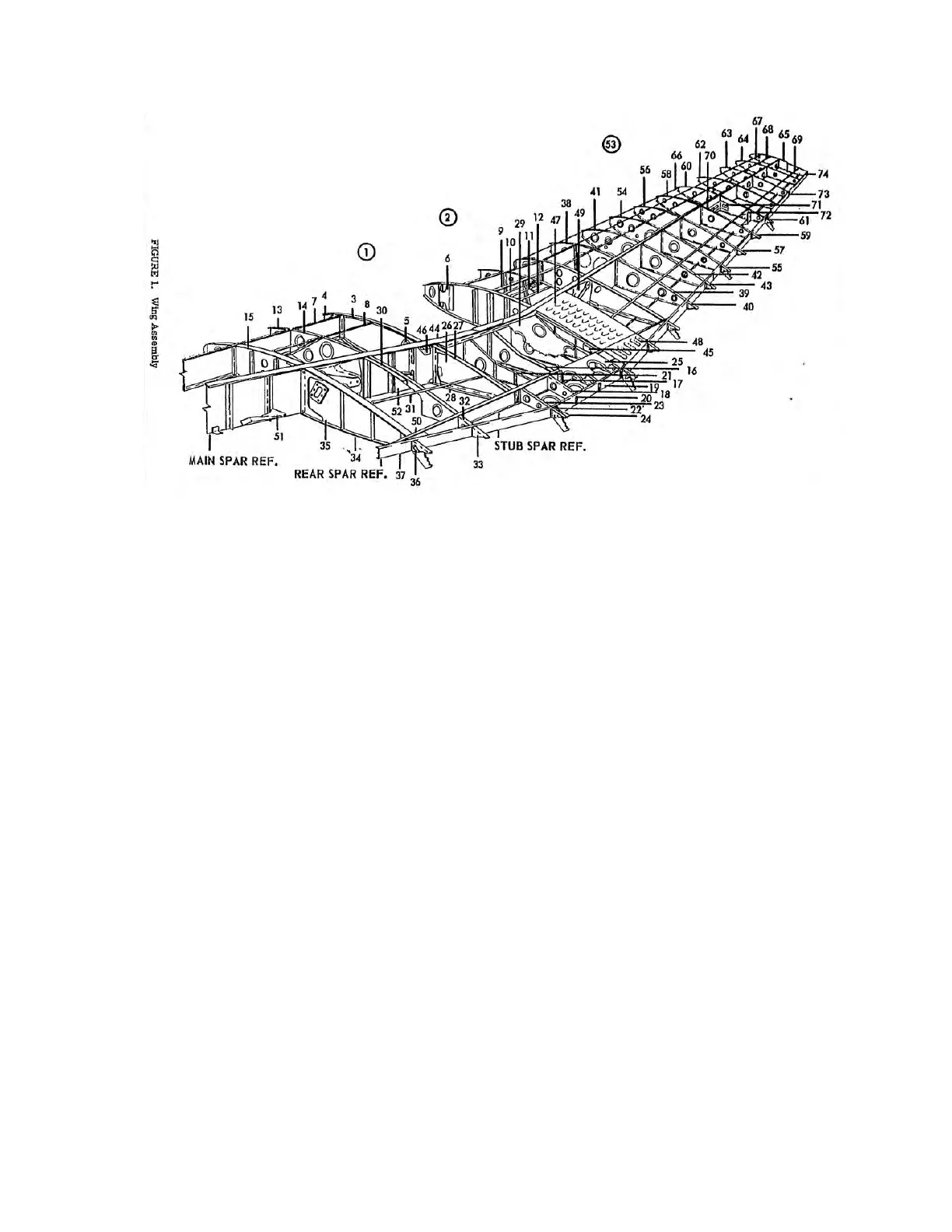
M20 Wing Structure
The spar is a single piece spar running from end to end under the rear seats with the ribs
attached to the spar. The original fuel tanks were part of the structure, but have since had fuel
bladders added.
Control surfaces have extruded-spar construction with stressed skins riveted to the spars
and ribs. Dual control wheels accompany the conventional flight controls. The pilot's rudder
pedals have toe brakes linked to individual hydraulic cylinders that supply pressure to the
hydraulic disc brakes on each main gear wheel. Removable co-pilot rudder pedals are standard
equipment
LANDING GEAR SYSTEM
The standard landing gear system in all models through 1968 was manually operated.
Immediately after construction, the Club’s aircraft had its manual landing gear replaced with an
electric gear system.
Rubber discs in the gear leg assemblies absorb the shock of taxiing and landing. Single-
disc self-adjusting hydraulic brakes are featured on the main gear. There are only toe breaks on
the pilot side rudder pedals. An airspeed-actuated safety-switch in the pitot system prevents
electric gear retraction on takeoff until a safe flying speed is attained (Note: This airspeed safety
switch is fundamentally different from a squat switch). A gear-throttle warning horn is operated
by a detent switch on the throttle which sounds when the throttle is set for 12 inches or less of
manifold pressure and the landing gear up.
The landing gear system has a steerable nose wheel. The nose gear steering system
consists of a steering horn on the gear leg linked to the rudder pedals by push-pull tubes and bell
cranks. Gear retraction automatically disengages the steering mechanism from the nose wheel
and a centering cam aligns the nose wheel for entry into the wheel well.
The gear position is indicated in several ways. There is a red in-transit light that lets you
know when it is in transit, and there is a green down light. The red in-transit light will go out