www.miinet.com Moore Industries-International, Inc.
- 28 -
User’s Manual
238-741-00K
May 2019
Section 3 - Installation and Wiring
Instructions in this section and others may require special precautions to ensure the safety of the
personnel performing the operations. Notes, Cautions and Warnings that may cause potential
safety issues are indicated throughout this manual by symbols, please refer to Page 3 of this
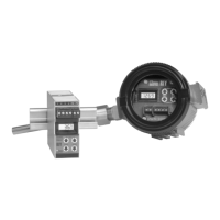
manual to view and familiarize yourself with these safety message symbols. Figures 3.2 through
3.7 show the various housings and their dimensions.
Note: Make sure to calibrate and bench check the instruments prior to installation. Also, install
all instruments in their intended application before making any electrical connections. For
DIN rail mounted instruments, allow enough room for pivoting instruments vertically on the rail
for removal in applications involving multiple banks of units. To remove the unit from the DIN
rail you will need a simple tool such as a straight blade screwdriver. Insert the blade of the
screwdriver into the cavity at the bottom of the locking mechanism and rotate it. This will release
the locking mechanism from the DIN rail and allow you to remove the unit.
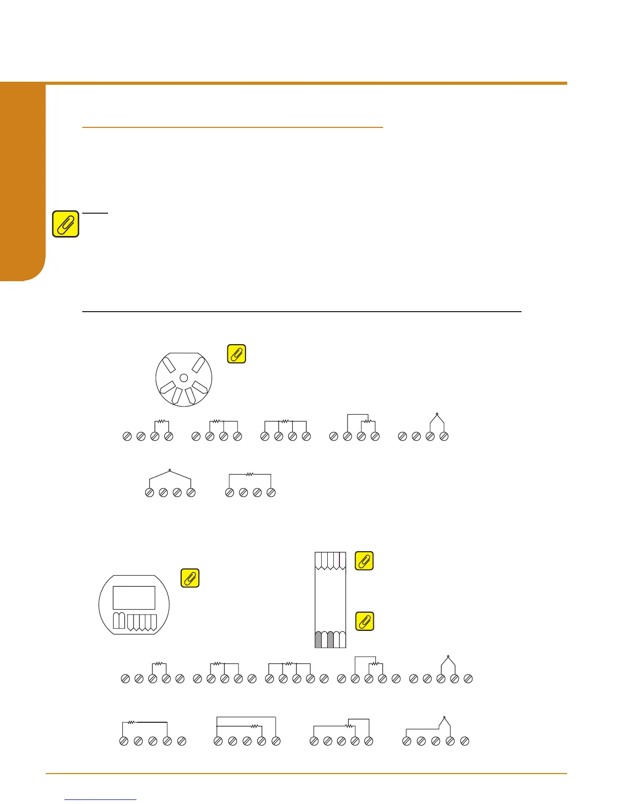
Figure 3.1. Terminal Designations
Terminal Designations
TB1 TB2 TB3 TB4
2W RTD / Resistance 3W RTD / Resistance
TB1 TB2 TB3 TB4
4W RTD / Resistance
TB1 TB2 TB3 TB4
POTENTIOMETER
TB1 TB2 TB3 TB4
2W RTD / Resistance
TB1 TB2 TB3 TB4
POTENTIOMETER
TB1 TB2 TB3 TB4 TB5
POTENTIOMETER
TB1 TB2 TB3 TB4 TB5
4W RTD / Resistance
TB1 TB2 TB3 TB4 TB5
3W RTD / Resistance
TB1 TB2 TB3 TB4 TB5
2W RTD / Resistance
TB1 TB2 TB3 TB4 TB5
THERMOCOUPLE / mV
TB1 TB2 TB3 TB4 TB5
+
-
TB1 TB2 TB3 TB4
THERMOCOUPLE / mV
+
-
TB1 TB2 TB3 TB4 TB5
2W RTD / Resistance
THERMOCOUPLE / mV
TB1 TB2 TB3 TB4
+
-
TB1 TB2 TB3 TB4 TB5
THERMOCOUPLE / mV
+
-
Sensor 1
Sensor 1
Sensor 2
Sensor 2
TB1 TB2 TB3 TB4 TB5
3W RTD / Resistance
-PS
+PS
-PS
+PS
THZ
3
HPP
THZ
3
DIN
TDZ
3
TB1
TB2TB3 TB4 TB5
TB2
TB3
TB4
TB1
-PS
+PS
TB1
TB2 TB3 TB4 TB5
THZ3 HPP (4 Terminals) Input Connections
TDZ3 HP and THZ3 DIN (5 Terminals) Input Connections
Note: THZ
3
[HPP] (see gure 3.4) – When using two input sensors, Sensor 1
can be congured as 2-wire or 3-wire sensor. Sensor 2 is then restricted to
a 2-wire sensor.
Note: THZ
3
[DIN] (see gure 3.2) - When
using two input sensors you are
limited to 2-wire and/or 3-wire sensors.
4-wire sensors (RTDs) cannot be used.
Note: TDZ
3
– When using two input
sensors you are limited to 2-wire
and/or 3-wire sensors. 4-wire sensors
(RTDs) cannot be used.
GND
Note: *GND is Case Ground terminal
used for -AIS option only.
Programmable Smart HART Temperature Transmitter
THZ
3
/ TDZ
3
SECTION 3