3.e Water connection
Connect the water heater to the water supply.
From the front, the cold water input is on the right and the hot water output is on the left.
Insert the filter into the water valve input fitting.
Remove the plastic cap from the water outputs fitting before connecting it to the water supply.
3.f Flue Gas
For output of flue gases refer to the regulations in force including
any updates. See page 3.
The water heater must be connected to a suitable flue terminal. The
following must be observed:
- The flue must be installed vertically – through the roof of the
holiday home
- The diameter of the flue terminal must match that of the water
heater (110mm)
- The overall flue length from the top of the water heater to the top
of the external flue must be at least 600mm. The distance from
the external roof surface to the top of the external flue must be at
least at least 250mm.
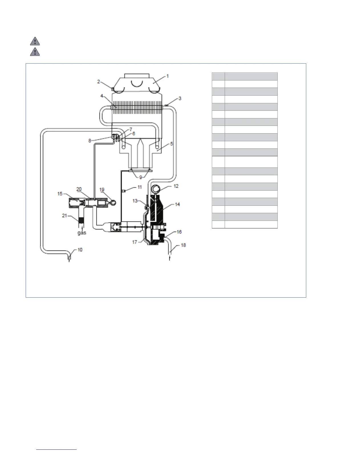
Flue gas safety device
This product is equipped with a flue gas safety device. The device
ensures the flue gases leave the water heater safely via the flue. The
flue safety device marked as 2 in Fig.6 is a flue gas safety device
that will interrupt the flow of gas to the water heater burner and pilot
light in the event that there is a total or partial blockage in the flue
that does not allow the flue gases to leave safely. The device will also
operate if the design or length of the flue is not correct. This stat will
reset when it has cooled down due to the technical issue being resolved
thus allowing the water heater to operate as normal.
If the flue gas safety device is faulty it will need to be replaced
before the water heater will function again. The stat must not be
removed or altered in any way otherwise the operation of the water
heater may become dangerous.
1
Flue diverter hood
2
Flue gas safety device
3
Hot water limit thermostat
4
Heat exchanger
5
Burner
6
Ignition electrode
7
Thermocouple
8
Pilot burner
9
Main burner injectors
10
Hot water output
11
Burner pressure test point