1. OPERATION
1.a. Function
The water heater is designed to produce instantaneous hot water. The hot water is delivered to several outlets around the home. If more
than one outlet is used at any one time the delivery of hot water will be reduced at each outlet. The Water heater has 2 main controls:
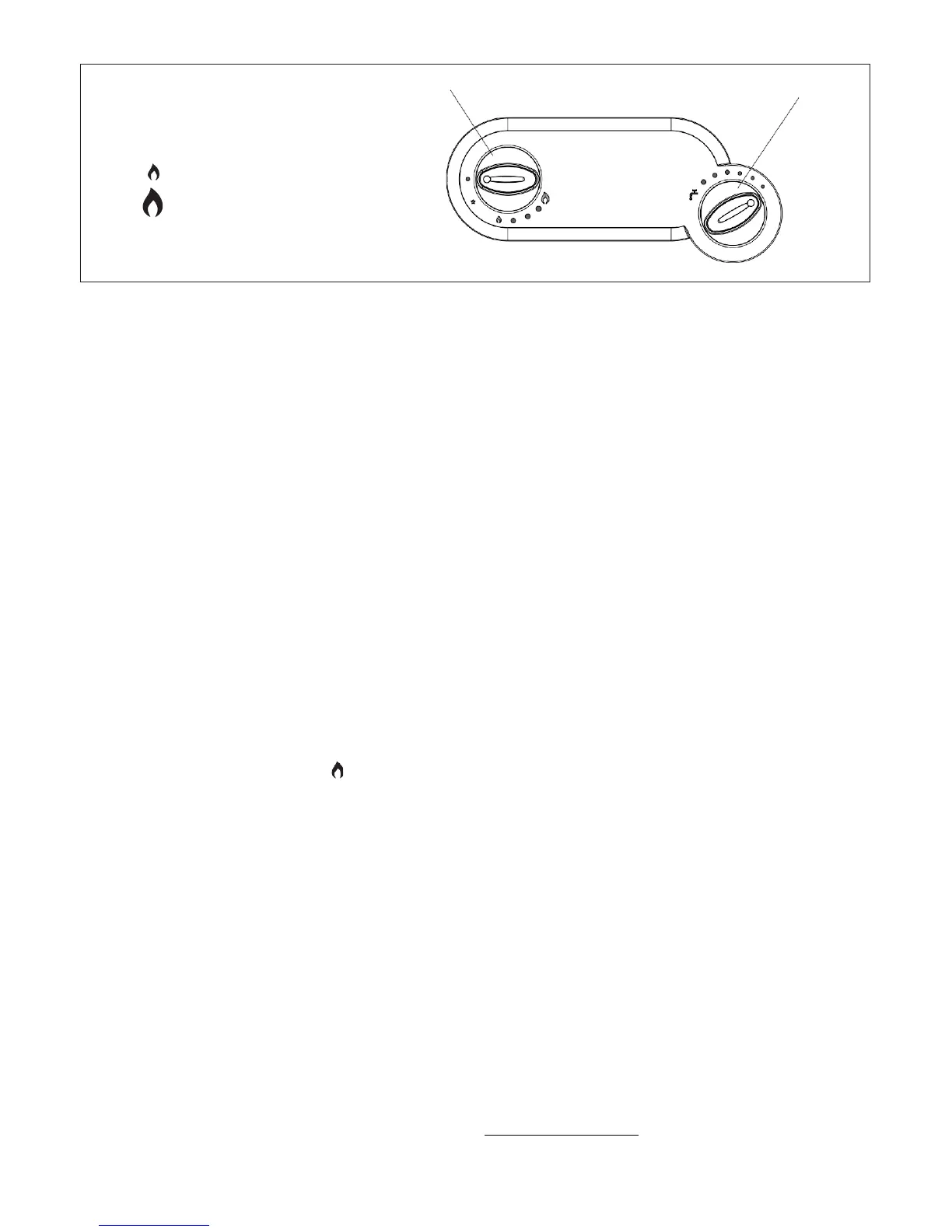
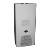
- A gas control knob - “A” in fig 1
- A water temperature control knob – “B” in fig 1
The minimum gas level in fig. 1 will provide approximately 50% of the available power. Turning the gas control knob counter- clockwise will
increase the power level between 50% and 100%. This function may be useful to vary the temperature of the water supplied.
The water temperature selector allows water to be supplied anywhere between 50% and 100% of the water heater’s capability. In effect the
selector reduces the water flow through the heater to the taps to increase the water temperature and correspondingly increases the water
flow to reduce the water temperature.
In the UK the normal positions for the controls are:
- Gas control – always set to 100% (fully counter clockwise)
- Water control set to 100% (fully clockwise) during the winter months
- Water control set to between 100% and 50% during the summer months to suit the customer’s preference for hot water temperature
1.b Usage
Ensure that the appliance gas isolation valve and all water taps are switched off
- Turn on the main external gas supply on the bottle or tank
- Light other gas appliances such as the cooker hob or fire and allow them to run for 30 seconds- this is to purge the gas system of air
- Open the appliance gas isolation valve, placed immediately below the water heater on the gas input pipe
- Rotate knob A to the on position (
), press the knob down all the way and keep it pressed
- Press the piezo electric button that is located under the water heater on the left-hand side until the spark ignites the pilot flame. The flame
can be seen through the viewing window on the front of the heater. When it ignites, keep the gas control knob (“A” in fig 1), pressed for
20-30 seconds. If the pilot does not stay lit when the knob is released, repeat the procedure
- Rotate Knob A towards the large flame ( ), during rotation it is necessary to keep the knob pressed down lightly until the final position
is reached
- From this moment the device is able to produce hot water on request. Opening the hot water tap causes the main burner to be ignited,
and inversely, by closing the hot water tap the main burner is switched off; but the pilot flame remains switched on for future requirements
- If the main burner or pilot flame is accidentally turned off, the gas valve automatically blocks the output of gas within 60 seconds so to
avoid any danger. To return the device to an operational mode, repeat the steps above
The machine is switched off by rotating knob A to the OFF position (●).
When the water heater is not used for long periods close the appliance gas isolation valve or the LPG gas valve on the bottle/tank.
For the best operational results it is recommended to have a Gas Safe Engineer or other qualified personnel service the machine at least
once a year.
PRECAUTIONS TO BE TAKEN AGAINST FROST AND FREEZING CONDITIONS
If there is a possibility that the area where the appliance is installed could reach below 0°C, the device must be emptied of all water.
During cold spells, if your appliance is located in a place exposed to frost and freezing conditions, it must be drained down in the following
way:
- Turn off the home’s water inlet stop tap.
- Disconnect the water supply pipe from the home
- Open any drain cocks located on the hot/cold water pipework under the home
- Turn on all hot and cold water taps
- Turn appliance water temperature selector fully anticlockwise
- Disconnect the cold water inlet to the water heater
- Full details of winterisation can be found under “troubleshooting” at www.morcoproducts.co.uk
- A summary can be found on page 13 of this manual
To use the appliance again reverse the above procedure
maximum gas level
B = Water temperature selector
fig. 1
B
A = Gas control on/off
● off position
activation position
minimum gas level
A