10
SECTION 2 - GENERAL SPECIFICATIONS
2 SPECIFICATIONS
2.1 GENERAL SPECIFICATIONS
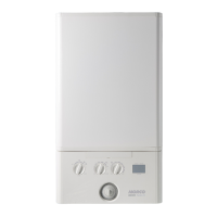
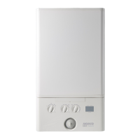
The Morco GB IV range of boilers are wall mounted, full
sequence, automatic spark ignition low water content, fanned ue,
high efciency condensing combination boilers.
Note. Due to the high efciency of the boiler a plume of water
vapour will be visible from the terminal during operation. The
boiler is supplied for use with Propane only at 37mbar (30 mbar
for DE/NL - refer to Countries of Destination) supply pressure. It
is particularly suitable for caravan holiday home and park home
use.
Maximum heat output in heating mode for the GB24 is 24.2 kW
with 24.2 kW available for hot water production.
Maximum heat output in heating mode for the GB30 is 24.2 kW
with 30.3 kW available for hot water production.
The boiler can be supplied with a standard concentric ue with
additional extensions, ue deector and vertical ue kits available
as optional extras. The only ue that can be tted are those
detailed in this instruction manual.
The boiler is suitable for connection to fully pumped, sealed
heating systems ONLY. Adequate arrangements for completely
draining the system by provision of drain cocks must be provided
in the installation pipework.
The boiler contains the following components:
Cast Aluminium Heat Exchanger
Domestic Hot Water Plate Heat Exchanger
Diverter Valve
Circulating Pump
Pressure Gauge
Pressure Relief Valve and Central Heating Expansion Vessel
Automatic Bypass
Daily Pump and Diverter Valve Exercise
Mechanical 24hr Timer
The boiler temperature controls are visible, located in the control
panel. These enable the user to control both CH and DHW
temperatures independently. Operating and fault codes are
displayed on the status panel.
8
11
18
5
19
9
12
4
15
6
2
1
13
7
3
14
10
16
17
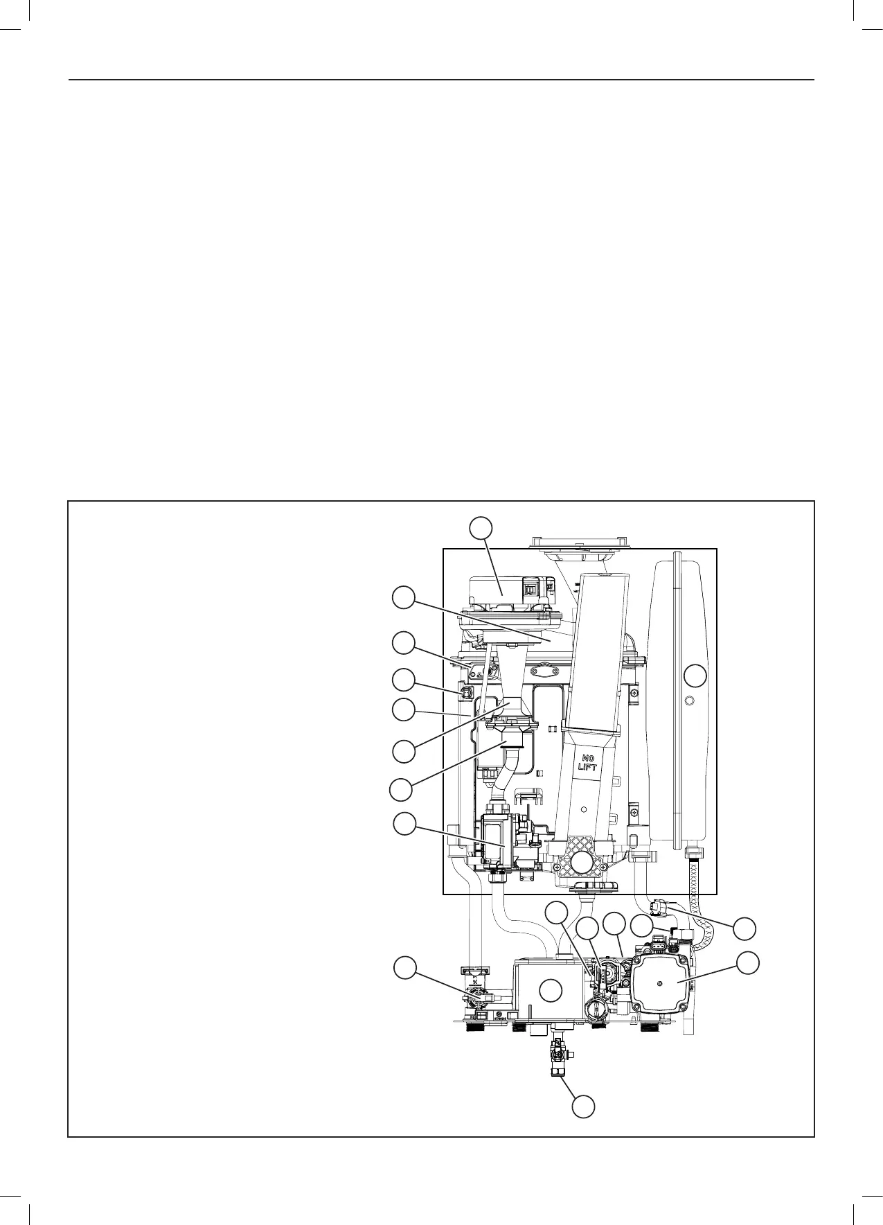
1. Expansion Vessel
2. Pump
3. Pressure Relief Valve
4. Water Pressure Switch
5. Flow Thermistor
6. Return Thermistor
7. Diverter Valve
8. Fan
9. Venturi
10. DHW Plate Heat Exchanger
11. Ignition / Detection Electrode
12. Gas Valve
13. Siphon / Trap
14. DHW Flow Turbine
15. Sump Cover
16. Injector Housing
17. Gas Cock
18. Burner
19. Cast Aluminium Heat Exchanger
2.2 SCHEMATIC DIAGRAM


 To Next Page