16
SECTION 5 - INSTALLATION INSTRUCTIONS
5 INSTALLATION INSTRUCTIONS
5.1 BOILER PACKAGING
The boilers are supplied in different packagings:
• Boiler
• Flue System (separate)
5.2 FITTING/MOUNTING THE BOILER
Decide where the boiler is to be xed on the wall, taking into
account installation requirements detailed in previous section.
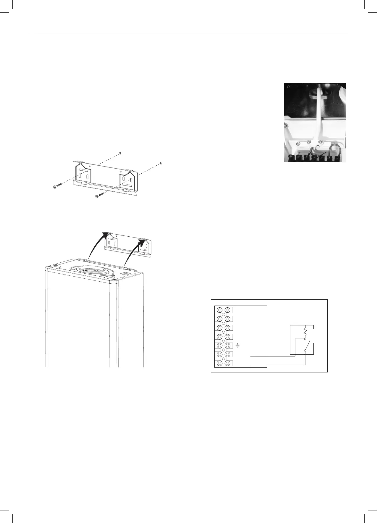
1. Screw the wall mounting plate to the wall choosing one of the
two sets of slots in left and right bank. Ensuring that at least
one of the screws is tted into a top slot.
2. Lift the boiler onto the wall mounting plate, locating it over the
two tabs.
Note.Ifpresent,removethebottomendsupportpackaging
andensureallplasticplugsareremovedfromCH&DHW
connections.
5.3 WIRING INSTRUCTIONS
WARNING: THIS APPLIANCE MUST BE EARTHED
Connections must be made in such a way that allows complete
isolation of the electrical supply, e.g. double pole switch with
3mm contact separating in both poles.
N
L
N
ROOM
STAT/
TIMER
Room
Stat
230VAC Feed
230VAC Return
5.4 INTERNAL WIRING
The boiler has been pre-tted with a 3 amp fused approved
moulded 3 pin and ying lead for use with 230V 50Hz.
If the supply cord is damaged, it must be replaced by the
manufacturer, its service agent or similarly qualied persons in
order to avoid a hazard.
The plug should be used with an
unswitched/shuttered socket outlet
complying with BS1363.
The boiler comes pre-tted with a link
wire between the room thermostat/
timer connections on the terminal strip.
This creates a permanent call for heat
and must be removed when adding a
room thermostat.
5.5 ROOM THERMOSTAT - WIRING
To t a room thermostat proceed as follows:
1. Ensure that the electrical supply to the boiler is isolated before
proceeding.
2. Remove the two screws beneath the ap on the front of the
boiler and lower the front panel.
3. Remove the pre-tted link wire between the Room stat/timer
terminals.
4. Pass the cable through a grommet, secure with the cable
clamp and connect the room stat as shown in the diagram
below.
5. If room stat has a neutral connection, connect this to terminal
N (load) in the fused spur.
6. Carry out all necessary electrical checks.
7. Raise the front panel and relocate the two screws under the
small ap.
8. Check operation of room stat if possible.
5.6 OPENTHERM WIRING
To t an optional Opentherm Controller proceed as follows:
1. Ensure that the electrical supply to the boiler is isolated before
proceeding.
2. Remove the screw beneath the ap on the front of the
boiler, and lower the front panel.
3. Remove the pre-tted link wire between the Opentherm
terminals on the right hand side of the front panel.
4. Pass the two wires from the Opentherm controller through
a grommet, and connect one to each of the two Opentherm
terminals.
5. Raise the front panel and relocate the screw.
6. Check operation if possible.
Example of fixing
Cable
Clamp

 Loading...