17
SECTION 5 - INSTALLATION INSTRUCTIONS
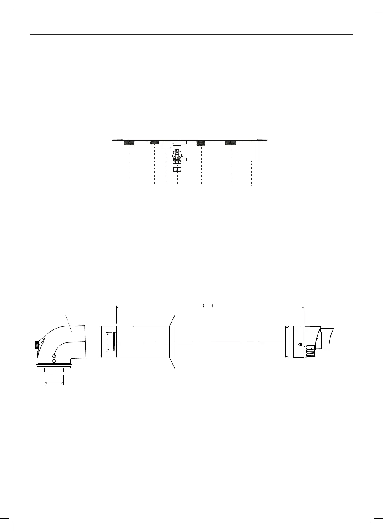
5.7 WATER AND GAS CONNECTIONS
Ensure all boss blanking plugs are removed before making any connections.
Each valve must be tted to the correct boss as shown in diagram below
Do not subject any of the isolating valves to heat as the seals may be damaged.
Ensure that the green bre washer is used on the CH ow connection.
IMPORTANT - The gas service cock is sealed with a top hat washer - DO NOT subject to heat.
Pressure Relief Valve (PRV) - Located at the bottom right hand side of the boiler connection via a 15mm diameter stub pipe.
Use a replaceable connection to ease the replacement of the valve if required.
Ensure a safe discharge point using temperature and pressure resistant materials.
5.8 AIR / FLUE SYSTEMS
The ue system is part of the appliance and is approved as such. Only use the ue systems supplied by Morco.
The standard ue kit (RSF303) for the Morco GB IV range is a 600mm as shown below. There is also a 900mm kit available
(RSF305).
600
Turret
60
60
100
CH FLOW
DHW OUTLET
COND. DRAIN
GAS INLET
DHW INLET
CH RETURN
PRV
Part No. RSF303
The minimum cut length is 138mm (includes 30mm into elbow)
The maximum allowable length using extensions (RSF341) is:
GB24 IV - 8m (minus any ue kit options)
GB30 IV - 7m (minus any ue kit options)
All dimensions in mm
 Loading...